JVC VN-V225VPU Read Me First
JVC VN-V225VPU - Network Camera - Pan Manual
 |
View all JVC VN-V225VPU manuals
Add to My Manuals
Save this manual to your list of manuals |
JVC VN-V225VPU manual content summary:
- JVC VN-V225VPU | Read Me First - Page 1
VN-X235VPU is a high definition surveillance camera that uses high resolution CCD sensors with 4 times the pixel count of VN-V225VPU. Thank you for purchasing this JVC product. Before operating this unit, please read the instructions carefully to ensure the best possible performance. Ⅵ This manual - JVC VN-V225VPU | Read Me First - Page 2
VN-X235VPU, you can perform PTZ operation and configure PTZ related settings. T For details, please refer to [INSTRUCTIONS install the open source codec "ffdshow". You can download "ffdshow" from the Internet. JVC -ROM ● Warranty Card (For USA) ● Service Information Card (For USA) ● Template ● Wrench
-
 1
1 -
 2
2
 |
 |
VN-X235VPU is a high definition surveillance camera that uses high resolution CCD sensors with 4 times
the pixel count of VN-V225VPU.
Thank you for purchasing this JVC product.
Before operating this unit, please read the instructions carefully to ensure the best possible performance.
±
The latest version
Please visit V.NETWORKS web site to check the latest firmware at
(The latest firmware can be found on V.NETWORKS
B
download page)
Installation
Setting Up the Camera
Mounting the Camera
Mount the camera to the ceiling or wall.
To mount on a wall, perform the same procedures below but replace the word “ceiling” with “wall”.
Cable Connection
For safety reasons, turn on the power only after all the connections are completed.
When power is supplied to the camera, the [STATUS] indicator lights up. The indicator lights up in orange during
startup and turns green when startup is complete.
Processes after connection
Fill up the piping hole and mounting hole with sealant and insert the silica gel.
Adjusting Images
When the camera is mounted, adjust the image settings while looking at the actual image.
Before touching the body of the camera, make sure to touch the metal surface of the [MONITOR] terminal to
discharge the static electricity from your body. The static electricity may cause the camera to malfunction.
Mounting the Dome Cover
K
Continues on the reverse page
±
This manual contains the basic instructions for using this unit.
Please refer to [INSTRUCTIONS (Setting)] (pdf) and [INSTRUCTIONS (Installation)] (pdf) in the CD-ROM
supplied with this product for description on the detailed usage of this unit.
For the latest information, please refer to the
A
README
B
file in the CD-ROM supplied with this product.
●
The supplied CD-ROM includes [INSTRUCTIONS (Setting)] (pdf), [INSTRUCTIONS (Installation)]
(pdf), [API Guide] (pdf), [VSIP Guide] (pdf)
,
[Search tool] and [White Spot Correction Tool].
±
How to read this READ ME FIRST
●
JVC holds the copyright to this manual. Any part or all of this manual may not be reproduced without prior consent
from the company.
●
Windows is a registered trademark of Microsoft Corporation in the U.S.
●
Product names of other companies described in this manual are trademarks or registered trademarks of the
respective companies. Symbols such as
²
,
³
and
´
are omitted in this manual.
●
Design, specifications and other contents described in this manual are subject to change for improvements without
prior notice.
Mounting the Camera
FIXED IP DOME CAMERA (Vandal Resistant)
VN-V225VPU
FIXED MEGAPIXEL IP DOME CAMERA (Vandal Resistant)
VN-X235VPU
READ ME FIRST
LST0849-001C
1
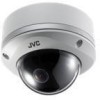
Remove the dome cover with the wrench provided (Screws x3)
2
Grab the inner dome and remove it from the catches (x3)
Catches
(x3)
Inner dome
Dome
cover
Fall
prevention
wire
(not
removable)
Camera
Wrench (provided)
2
8 mm
2 mm
1
3
1
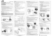
Use the provided template to make a
R
30 mm (1-1/8 inch) hole in the ceiling.
2
Mount the fall prevention wire that connects the camera to the ceiling.
T
Fall prevention wire is not provided. Prepare a wire with due consideration of the length,
strength, pull factor and material (insulative).
A
Unscrew the mounting screw for the fall prevention wire beneath the camera and mount
the fall prevention wire.
B
Mount the fall prevention wire to a strong location.
3
Mount the camera to the ceiling
Pull out the cables from the ceiling and the cables from the camera towards the lens as shown,
face the (
D
) mark in the shooting direction, then mount the camera to the ceiling. To mount on a
wall,
mount the camera such that the (
D
) mark is facing upwards.
T
Screws for mounting the camera are not provided. Use the appropriate type of screws
according to the material of the location for mounting.
Note
:
●
To mount the camera using electrical box or piping, please refer to (
A
[INSTRUCTIONS
(Installation)]) in the bundled CD-ROM.
±
Fall prevention wire
6 mm and below
R
12 mm and below
R
4.1
_
6.5 mm
Fall prevention wire (not provided)
R
4 mm screw ×2 (not provided)
Base
R
30 mm (1-1/8 inch)
Shooting
direction mark
3
1,2,4
5
1
Connect the alarm cable
Connect the alarm cable to an external device, such as a sensor or buzzer.
2
Connect to audio cable
(Recommended shield cable)
3
Connect the LAN cable
T
To use the PoE power supply, connect to a PoE-compatible device and supply the power from the
LAN cable.
Note
:
●
When using a heater unit (sold separately: KA-ZH215U), PoE power supply does not work
for the heater unit (KA-ZH215U). Be sure to use an AC 24 V power supply.
●
Connecting to HUB
: Use a straight cable
●
Connecting to a computer
: Use a cross cable
4
Connect the power cable
Power can be supplied to this unit either by connecting to an AC 24 V power supply or using
PoE. (To use PoE
A
[
3
Connect the LAN cable])
Note
:
●
The power supply cable includes cable of the same color as the alarm cable. Check properly before
connecting.
●
Make sure that power is supplied using only one of the above methods at any one time. Connecting
simultaneously using the power cable and to PoE via a LAN cable may cause the camera to break
down or malfunction.
●
By default the IP addresses of all the cameras are set to 192.168.0.2. If the power of multiple
cameras within the same LAN environment are turned on at the same time, the IP addresses of the
cameras overlap, thus preventing proper access. As such, make sure to turn on the power of the
cameras one by one and set the IP addresses such that there is no overlapping.
±
Type of cable
±
Power cable
Connection distance when using 2-core VVF cable (Reference values)
5
Wind the waterproof tape
Note
:
●
For cables that are not used, be sure to wrap the ends individually with insulating tape.
Alarm cable to use (Recommended shield cable)
●
Length of 50 m or shorter
●
UL1007, UL1015 or equivalent products
●
AWG#22 to AWG#18 or equivalent products
LAN cable to use
●
STP (Recommended shield cable)
●
Length of 100 m or shorter
●
Category 5 and above
Type
Color
Signal Name
Alarm cable
Black
(shielded cable)
Red
Alarm input 1
Brown
Alarm input 2
Orange
Alarm output 1
Yellow
Alarm output 2
Black
GND
Audio cable
Brown
(shielded cable)
White
MIKE IN
Yellow
GND
Black
(shielded cable)
White
LINE OUT
Yellow
GND
Power cable
Red (unshielded cable)
AC 24 V Power Supply
Black (unshielded cable)
Conductor diameter (mm)
R
1.0 and above
R
1.6 and above
R
2.0 and above
Maximum connection distance (m)
130
340
540
Maximum connection distance (m) with
Heater (KA-ZH215U)
40
120
180
Caution
The rated power of this product is AC 24 V, 50 Hz/60 Hz. Make sure to use it with the correct
voltage.
Be sure to use an AC 24 V supply that is insulated from the primary power source.
Supplying a power beyond the rated value may result in failures, smoke or fire. If the camera
breaks down, turn off the power and contact our service center immediately.
When a power beyond the rated value is supplied, the internal components may be
damaged even if no abnormality is found on the appearance and operation of the camera.
Please send to your nearest JVC dealer immediately for servicing (charged separately).
10BASE-T/100BASE-TX(PoE)
terminal
LAN cable
Wind the
waterproof
tape
Solder welding
or crimping
Wind the
insulation tape
LAN cable stopper (x2)
Space for heater
Memo
:
●
When mounting the heater unit (sold
separately: KA-ZH215U), please refer to
the KA-ZH215U [INSTRUCTIONS].
2
1
1
Use sealant (GE silicon) to fill up the mounting holes (x2) to which
the piping hole and screws are mounted
Note
:
●
Make sure the holes are completely sealed up. Water or moisture may seep in and fog up the
lens and dome cover.
2
Insert the silica gel (provided)
Note
:
●
Please make sure that rain does not seep into this unit when mounting on rainy days.
●
Be sure to use the silica gel (provided). Failure to do so may fog up the camera lens and dome cover.
●
If field angle is not adjusted immediately after mounting the camera, insert the silica gel (provided) after
adjustment. The silica gel (provided) will lose its effectiveness if it is exposed to the air for a long time.
Sealant
(GE silicon)
Silica gel (Provided)
Lug plate
Space for inserting
the silica gel
T
This illustration is for the
purpose of explanation, and
does not represent the
actual camera.
1
2 , 6
3
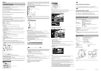
1
Connect the [MONITOR] terminal to the test monitor
2
Set the [MONITOR OUT] selector switch to
A
N
B
or
A
P
B
, turn on the
power or press and hold the [RESET] button for less than 2 seconds
●
The camera reboots. (approximately 1 minute)
●
During the restart, the [STATUS] indicator lights up in orange.
●
Set to
A
N
B
when connecting to a NTSC monitor or set to
A
P
B
when connecting to a PAL monitor.
3
Adjust the shooting direction of the camera
Adjust the camera for pan, tilt and rotation, and face the camera towards the subject.
[MONITOR] terminal
75
K
terminated
Test monitor
Memo
:
●
Rotate both pan and rotation ±175
µ
from the positions aligned with the camera’s shooting
direction mark, pan center mark and rotation center mark. Be sure to hold the rotation control
and adjust the rotation without holding the lens section.
●
After adjusting the field angle, tighten and secure the tilt fastening screw so that the field angle
will not be misaligned.
Note
:
●
Moving the camera when it has exceeded the adjustment range may cause its performance to
deteriorate.
●
As the tilt and rotation range of this unit is wide, part of this unit may be reflected in the shooting
screen depending on the field angle and direction.
●
Do not hold the lens section when adjusting the camera direction. The lens section may be
damaged if you apply force to it.
4
Adjust the image size
Loosen the fastening screw of the zoom adjustment ring, move the ring to the left and right to
adjust the image size. After adjusting, fasten the screw with pressing it slightly toward the lens
direction (toward
the shooting direction).
Tilt: ±70
µ
Pan: ±175
µ
Rotation: ±175
µ
Shooting direction
mark
Pan center mark
Rotation center
mark
Rotation control (x4)
[MONITOR OUT] selector switch
[RESET] button
Tilt fastening screw
[STATUS] indicator
6
7
5
5
Roughly adjust the focus
A
Lift the focus adjust gear knob, and place the catch into B in the diagram
●
The gear is disengaged.
Note
:
●
If the gear is moved outwards from B, the shaft of the gear may shift. For details on how
to return the gear to the original position, refer to (
A
[INSTRUCTIONS (Installation)]) in
the supplied CD-ROM.
B
Loosen the fastening screw of the focus adjustment ring, move it to the left and
right to adjust the focus.
6
Fine adjust the focus
A
Press the [RESET] button for more than 2 seconds but less than 5 seconds.
●
The camera enters the focus adjust mode and the [STATUS] indicator blinks in green
and orange alternately.
●
The image is sharpened with the opening of the lens iris.
●
The center of the image is enlarged. (VN-X235VPU only)
●
After adjusting the focus, press the [RESET] button for more than 2 seconds but less
than 5 seconds to release the focus adjust mode.
B
Shoot the subject
C
Fine adjust the focus
●
Return the catch to A in the diagram, and then rotate the knob to adjust the focus to the
optimum position.
D
Rotate the focus adjust gear knob about one base pitch in the direction of the arrow
in the diagram.
●
This is to correct the focus shift when mounting the dome cover.
E
Hold the dome cover over the lens and check the focus
7
Hold and press the focus adjust gear between your fingers in the
direction of the arrows in the diagram, and tighten the fastening
screw of the focus adjustment ring
8
Set the [MONITOR OUT] selector switch to
A
OFF
B
, then press the
[RESET] button shortly (less than 2 seconds)
●
The camera restarts, and the focus assist mode is released.
Zoom adjustment ring
Focus adjustment ring
Focus adjust gear
One base pitch
Knob
A
B
Catch
Knob
A
B Catch
B
C
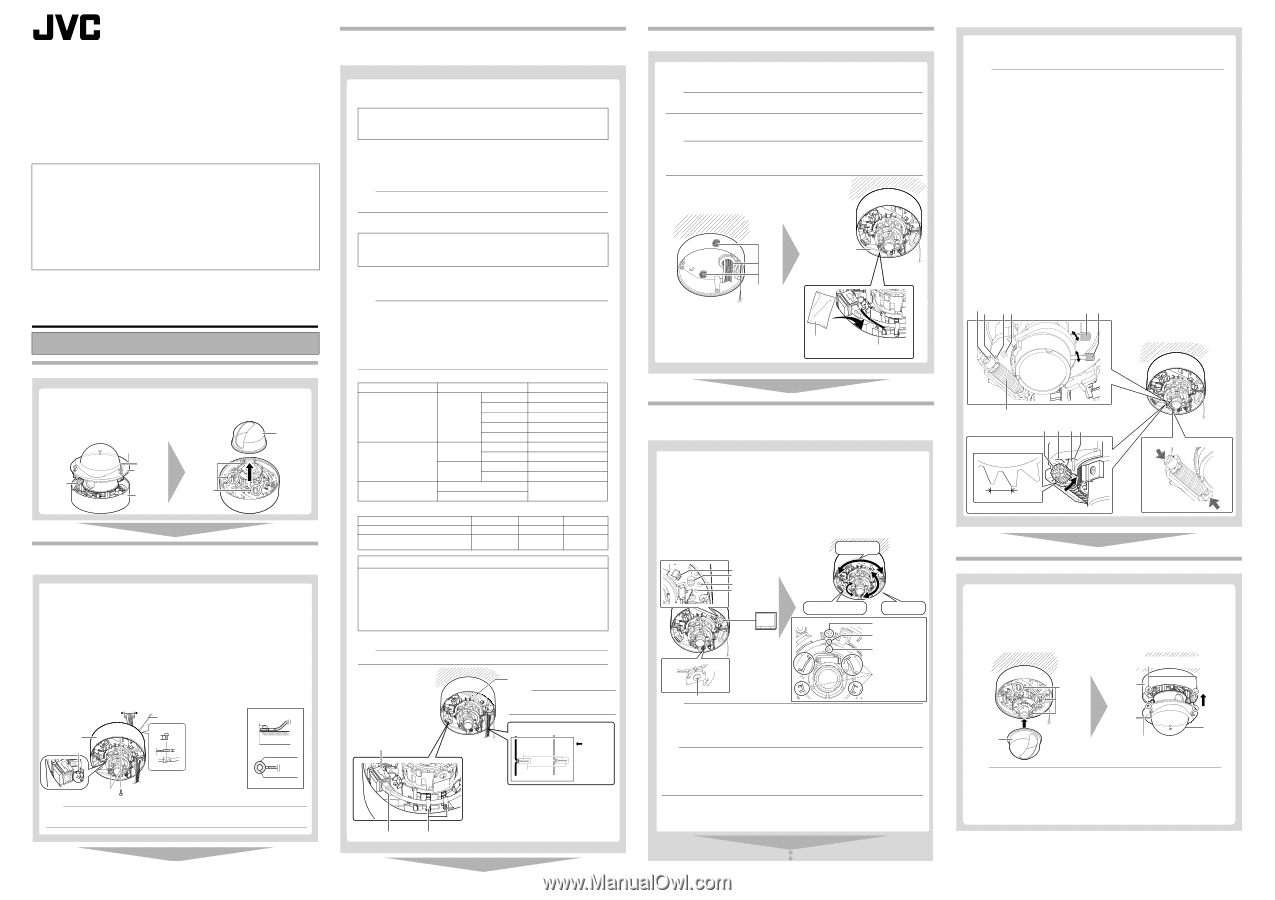
1
Mount the inner dome to the catches (x3)
2
Mount the dome cover
A
Remove and clean any dust or dirt on the dome cover.
B
Align the base with the position alignment marks (x3) on the dome cover and mount
the dome cover.
C
Tighten and secure the dome cover fastening screws (x3).
Catches
(x3)
Inner dome
Dome
cover
Base
Position alignment mark (x3)
Note
:
●
Check that the silica gel
(Provided)
has been inserted before mounting the dome cover.
●
Ensure that the dome cover is secured. Insecure mounting may increase humidity, fog up the
camera or the cover may drop.
●
When the cover is removed again after mounting the dome cover, check the field angle and re-
adjust the focus and field angle if necessary.
●
Make sure that the fall prevention wire of the dome cover is not caught between the dome cover
and the base. Otherwise, the anti-dust and waterproof function may not work properly.
Wrench (provided)