Jensen VM9312 Instruction Manual - Page 6
Pre-installation, Wiring, Final Installation, Final ISO-DIN Installation - wire harness
 |
UPC - 043258303707
View all Jensen VM9312 manuals
Add to My Manuals
Save this manual to your list of manuals |
Page 6 highlights
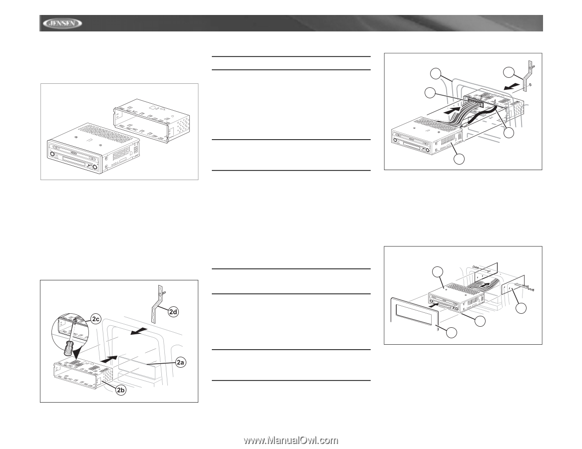
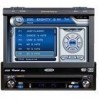
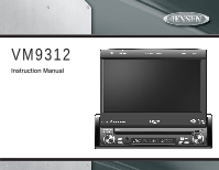
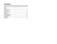
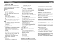
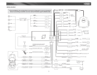
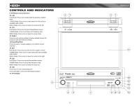
INSTALLATION Pre-installation 1. Press the metal levers on both sides to remove the halfsleeve from the radio. PREPARE RADIO BAND AS/PS PRELOSS/DAXUDIO VM9312 SRC DISP OPEN EJECT MUTE 2. Install the half-sleeve. a. Install adapter if necessary (optional). b. Install half-sleeve into adapter or dashboard (use only the supplied screws). Do not force the sleeve into the opening or cause it to bend or bow. c. Locate the series of bend-tabs along the top, bottom and sides of the mounting sleeve. With the sleeve fully inserted into the dashboard opening, bend as many of the tabs outward as necessary so that the sleeve is firmly secured to the dashboard. d. Install support strap to make the unit more stable. INSTALL HALF SLEEVE CAUTION! Be careful not to damage the car wiring. 3. Place the radio in front of the dashboard opening so the wiring can be brought through the mounting sleeve. Wiring Complete wiring as illustrated in the wiring diagram on page 3. Once the wiring is complete, reconnect the battery negative terminal. If there is no ACC available, connect the ACC lead to the power supply with a switch. NOTE: When replacing a fuse, be sure to use correct type and amperage to avoid damaging the radio. The VM9312 uses one 10 amp mini-ATM fuse, located in the black filter box in-line with the main wire harness. Final Installation After completing the wiring connections, turn the unit on to confirm operation (ignition switch must be on). If unit does not operate, recheck all wiring until problem is corrected. Once proper operation is achieved, turn off the ignition switch and proceed with final mounting of the chassis. 1. Connect wiring adapter to existing wiring harness. 2. Connect antenna lead. 3. Carefully slide the radio into the half-sleeve, making sure it is right-side-up, until it is fully seated and the spring clips lock it into place. NOTE: For proper operation of the CD/DVD player, the chassis must be mounted within 20° of horizontal. Make sure the unit is mounted within this limitation. 4. Attach one end of the perforated support strap (supplied) to the screw stud on the rear of the chassis using the hex nut provided. Fasten the other end of the perforated strap to a secure part of the dashboard either above or below the radio using the screw and hex nut provided. Bend the strap to position it as necessary. CAUTION! The rear of the radio must be supported with the strap to prevent damage to the dashboard from the weight of the radio or improper operation due to vibration. 5. Replace any items you removed from the dashboard. FINAL INSTALLATION 5 1 VM9312 4 BAND AS/PS PRELOSS/DAXUDIO VM9312 SRC DISP OPEN EJECT MUTE 3 2 Final ISO-DIN Installation 1. Remove trim ring. 2. Mount factory brackets on new radio using existing screws from old radio. 3. Slide radio chassis into dash opening and secure. 4. Reinstall dash panel. FINAL ISO-DIN INSTALLATION 3 BAND AS/PS PRELOSS/DAXUDIO VM9312 SRC DISP OPEN EJECT MUTE 4 1 2 2
-
 1
1 -
 2
2 -
 3
3 -
 4
4 -
 5
5 -
 6
6 -
 7
7 -
 8
8 -
 9
9 -
 10
10 -
 11
11 -
 12
12 -
13
-
14
-
15
-
16
-
17
-
18
-
19
-
20
-
21
-
22
-
23
-
24
-
25
-
26
-
27
-
28
-
29
-
30
-
31
-
32
-
33
-
34
-
35
-
36
 |
 |