Kenmore 31813 Owners Manual - Page 11
Converting, the Element, cont'd
 |
View all Kenmore 31813 manuals
Add to My Manuals
Save this manual to your list of manuals |
Page 11 highlights
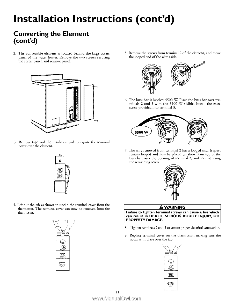
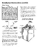
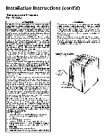
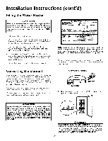
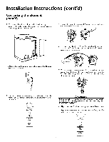
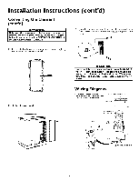
Installation Instructions (cont'd) Converting the Element (cont'd) 2. The convertible element is located behind the large access panel of the water heater. Remove the two screws securing the access panel, and remove panel. 5. Remove the screws from terminal 2 of the element, and move the looped end of the wire aside. 6. The buss bar is labeled 5500 W. Place the buss bar over terminals 2 and 3 with the 5500 W visible. Install the extra screw provided into terminal 3. 3. Remove tape and the insulation pad to expose the terminal cover over the element. IO @ nJn_r pcoo_ B_FC_E SE_WO:N¢ ------I 4. Lift out the tab as shown to unclip the terminal cover from the thermostat. The terminal cover can now be removed from the thermostat. 7. The wire removed from terminal 2 has a looped end. It must remain looped and now be placed (as shown) on top of the buss bar, over the opening of terminal 2, and secured using the remaining screw. _,WARNING I Failure to tighten terminal screwscan causea fire which can result in DEATH, SERIOUS BODILY INJURY, OR PROPERTY DAMAGE. 8. _l]ghten terminals 2 and 3 to ensure proper electricalconnection. 9. Replace terminal cover on the thermostat, making sure the notch is in place over the tab. 11
-
 1
1 -
2
-
3
-
4
-
5
-
 6
6 -
 7
7 -
 8
8 -
 9
9 -
 10
10 -
 11
11 -
 12
12 -
 13
13 -
 14
14 -
 15
15 -
 16
16 -
17
-
18
-
19
-
20
-
21
-
22
-
23
-
24
-
25
-
26
-
27
-
28
 |
 |