Kenmore 3247 Installation Instructions
Kenmore 3247 - Elite 36 in. Gas Cooktop Manual
 |
View all Kenmore 3247 manuals
Add to My Manuals
Save this manual to your list of manuals |
Kenmore 3247 manual content summary:
- Kenmore 3247 | Installation Instructions - Page 1
Follow the gas supplier's instructions. 0 If you cannot reach your gas supplier, call the fire department. m Installation and service must be performed by a qualified installer, service agency or the gas supplier. Gas Cooktop Dimensions 30" Min. (76.2 cm) _la 21/2" Gas Cooktop Cutout Dimensions - Kenmore 3247 | Installation Instructions - Page 2
with any appliance using gas and generating heat, there are certain safety precautions you should follow. You will find them in the Use and Care Guide, read it carefully. • Be sure your cooktop is instaJJed and grounded properly by a qualified installer or service technician. This cooktop must be - Kenmore 3247 | Installation Instructions - Page 3
be reduced by installing a range hood that projects horizontally a minimum of 5" (1 2.7 cm) beyond the bottom of the cabinets. Drawers Cannot Be Used with This Cooktop Since Burner Box Extends 3s/32'' (8.02 cm) Below Surface of Cou ntertop. 30 '_Cooktop 36 '_Cooktop 30'_(76.2 cm) 36'_(91.4 cm - Kenmore 3247 | Installation Instructions - Page 4
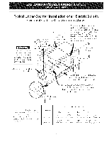
Typical Gas Cooktop Installation Over an Electric Built-in Oven Installed Under the Counter I_---- 18" (45.7 cm) Max.-----_ Manifold Cabinet 4" (10.2 cm) 120V/60Hz Grounded Outlet Pressure Regulator Right Side of Cabinet Manual Shutoff Valve (To be accessible for shut-off valve opera- tion) - Kenmore 3247 | Installation Instructions - Page 5
Gas Cooktop Installation Over an Electric Built-in Oven Installed Under the Counter" on previous page. 32" Min.** (81.3 cm) 36" (91.4 cm) 208/240 Volt grounded junction box for built-in Use 3/4" (1.9 cm) plywood, installed on two runners, flush with toe plate. Must be capable of supporting - Kenmore 3247 | Installation Instructions - Page 6
range should be I/2" or 3/4" pipe. OF UNIT Figure 3 Cooktop Installation 1. Visually inspect the cooktop for damage. 2. Set the cooktop into the countertop cutout. LP/Propane Gas Conversion This appliance can be used with Natural gas or LP/ Propane gas. It is shipped from the factory for use with - Kenmore 3247 | Installation Instructions - Page 7
in the same room as the cooktop and should be in a location that allows ease of opening and closing. Do not block access to the shutoff valve. The valve is for turning on or shutting off gas to the appliance. Manual Shutoff Valve Flare Union ÷ Nipple Off GAS FLOW _'_ Flexible Connector Pressure - Kenmore 3247 | Installation Instructions - Page 8
7) to minimize the possibility of electric shock hazard from the appliance. The wall receptacle and circuit should be checked by a servicing cooktop. Check Operation Refer to the Use and Care Guide packaged with the cooktop for operating instructions and for care and cleaning of your cooktop. - Kenmore 3247 | Installation Instructions - Page 9
rating of the burners, the type of fuel and the pressure the cooktop was adjusted for when it left the factory. Before You Call for Service Read the Before You Call for Service Checklist and operating instructions in your Use and Care Guide. It may save you time and expense. The list includes common - Kenmore 3247 | Installation Instructions - Page 10
PARA FUTURAS REFERENCIAS [F_ Si todas las instrucciones de este manual no son observadas a la letra, se puede ocurrir incendios cocinar para la conexi6n 318201470 (0606) Rev. A de la linea de suministro de gas. English - pages 1-9 NOTA: Se adjunta los diagramas de cables de esta plancha de - Kenmore 3247 | Installation Instructions - Page 11
artefactos a gas que generan calor, deben seguirse ciertas medidas de seguridad. Vienen con el Manual del Usuario. Lea atentamente el manual. ,,Aseg_rese que in Canada, con el Canadian Electrical Code, CSA C22.1 Parte I. • Los quemadores pueden encenderse manualmente durante una interrupci6n del - Kenmore 3247 | Installation Instructions - Page 12
con este espacio, se puede disminuir el peligro instalando una cubierta de cocina que se extienda horizontalmente en 5" (12.7 cm) minimo por sobre la parte inferior delantera en los armarios. No es posible utilisar cajones con esta parrilla de cocinar porqu_ la caja de empalme se extiende de 3s - Kenmore 3247 | Installation Instructions - Page 13
Instalaci6n tipica de la plancha de cocinar a gas pot encima de un homo el6ctrico empotrado instalado debajo del a tierra regulador de presi6n # 4" (10.2cm) Lado derecho del armario tA Valvula de cierre manual (Debe de ser accessible para el funciona-miento de la valvula de cierre) 13 - Kenmore 3247 | Installation Instructions - Page 14
de cocinar aprobantes. Vet "lnstalacion tipica de plancha de cocinar a gas por encima de un homo electrico empotrado instalado debajo del mostrador" ) ** Un minimo de 32" (81.3 cm) desde la parte superior del armario hasta la parte superior de las ruedas debe de ser mantenido. Tamano del homo 30 - Kenmore 3247 | Installation Instructions - Page 15
pasar a tray,s del soporte y hasta la parte de abajo del mostrador. Apri_telo hasta que el aparato manual de instrucciones para la instalaciOn en el paquete escrito "PARA LA CONVERSIONEN GAS PROPANO'. Siga las instrucciones que estan con los orificios. Para hacer la conversion del gas natural al gas - Kenmore 3247 | Installation Instructions - Page 16
con una Ilave de tuerca Figura 5 Monte el conector flexible del tubo del suministro de gas al regulador de presiOn en funcionamiento: 1. valvula de cierre manual 2. boquilla de 1/2" (1.3 cm) 3. adaptor de 1/2" (1.3 cm) 4. conector flexible 5. adaptator de I/2" (1.3 cm) 6. boquilla de 1/2" (1.3 cm - Kenmore 3247 | Installation Instructions - Page 17
de reparar la plancha de cocinar. Verifique la operacion Refiera al Manual del Usuario que viene con la plancha de cocinar para las Anillo de localizaci6n \ Tapa del quemadore Base del quemadore Abertura del gas Anillo del q Electrodo Figura 8 NOTA: No es necesario realizar ajustes - Kenmore 3247 | Installation Instructions - Page 18
letra del Iote que se encuentran en la plata, en todo pedido de partes o solicitud de informaci6n acerca de su plancha de cocinar. La plata de este artefacto. Lea la garantia y la informaciOn sobre el servicio en su Manual del Usuario para obtener el nOmero de tel_fono y la dirreciOn del servicio - Kenmore 3247 | Installation Instructions - Page 19
'M G AR LEFT FRONT LGN SW [NTENC DE FRENTE IZOU[ER]O LNTERALLU_ G AV CAUTION: iL] LABEL ALL WIRES PRIOR TO DISCONNECTION WHEN SERVICING CONTROLS _IRIM] E_OR CAN CAbbiE [_R{_ER A_ DANGEWOb - Kenmore 3247 | Installation Instructions - Page 20
C;_ [3LJ_N R ]ON ER Ob_',IDS_ OF NC [XU]DO UPROR I_JGiE rl'R[ L LJ_AGE E_RtJl EUR OP 8LRN V: ](} ER 0 JE'_ADC ':_, D£ EN(}_NI}I}O SUPE OI BOtJQ J E D' £L -U'_AGE 8LJL ER .'}1 U_N]R ] (}fl ] ][R QUEM_DQR DE ENC NOJDQ ,U° BOUG E D" _LLU_&G RULEU_ [ [OR }iR TOP BURN QN I TER QU bADO
-
 1
1 -
 2
2 -
 3
3 -
 4
4 -
 5
5 -
 6
6 -
 7
7 -
8
-
9
-
10
-
11
-
12
-
13
-
14
-
15
-
16
-
17
-
18
-
19
-
20
 |
 |

iNSTALLATiON
AND
SERVICE
MUST
BE
PERFORMED
BY A QUALiFiED
iNSTALLER.
iMPORTANT:
SAVE FOR LOCAL
ELECTRICAL
iNSPECTOR'S
USE.
READ AND
SAVE THESE iNSTRUCTiONS
FOR FUTURE
REFERENCE.
If the
information
in
this
manual
is
not
followed
exactly,
a fire
or explosion
may
result
causing
property
damage,
personal
injury
or death.
FOR YOUR
SAFETY:
--
Do
not
store
or
use gasoline
or
other
flammable
vapors
and
liquids
in
0
0
0
0
m
the
vicinity
of
this
or any
other
appliance.
WHAT
TO
DO
IF YOU
SMELL
GAS:
Do
not
try
to
light
any
appliance.
Do
not
touch
any
electrical
switch;
do
not
use any
phone
in
your
building.
Immediately
call
your
gas
supplier
from
a
neighbor's
phone.
Follow
the
gas supplier's
instructions.
If you
cannot
reach
your
gas supplier,
call
the
fire
department.
Installation
and
service
must
be performed
by
a qualified
installer,
service
agency
or
the
gas supplier.
Gas Cooktop
Dimensions
21/2"
30" Min.
(76.2 cm)
_la
Gas Cooktop
(6.4 cm)
Cutout Dimensions
,
tt
Figure
1
i_!_iiii_
_i_i_i_!iii!_i_i_
¸i_i_i!_!_!_i_i_i_i_i_i_!ii_!!!!!_i_i_i_i_i_i_i_i_i_i_i_i_
30" GasCooktop
30 (76.2)
213A(55.2)
4_A(10.8)
27(68.6)
19 (48.3)
36" GasCooktop
36 (91.4)
213A(55.2)
4_A(10.8)
33_/4
(84.5)
19(48.3)
u
30" GasCooktop
27Y4
(69.2)
273A
(70.5)
19_/8
(48.6)
19s/8(49.8)
8 (20.3)
36" GasCooktop
33_/4
(84.5)
333A
(85.7)
19_/8
(48.6)
19s/8(49.8)
8 (20.3)
All dimensions
are stated
in inches
and (cm).
Dimension H includes a 5" (12.7 cm) space underneath the cooktop
for connection
to gas supply line.
NOTE:
Wiring
diagrams
for
this
cooktop
are enclosed
in
this
booklet
Printed in United States
318201470
(0606) Rev. A
English - pages 1-9
Espar_ol - p_qginas 10-18
Wiring
Diagram
19-20