Kenmore 7540 Installation Instructions
Kenmore 7540 - Elite 36 in. Gas Manual
 |
View all Kenmore 7540 manuals
Add to My Manuals
Save this manual to your list of manuals |
Kenmore 7540 manual content summary:
- Kenmore 7540 | Installation Instructions - Page 1
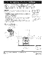
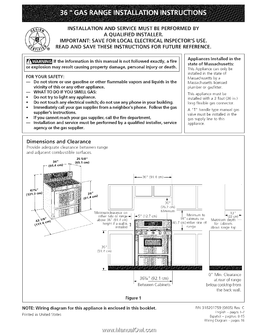
with a 3 foot (36 in.) long flexible gas connector. A "T" handle type manual gas valve must be installed in the gas supply line to this appliance. Dimensions and Clearance Provide adequate clearance between and adjacent combustible surfaces. 2S 5/8" 38" (65.1 cm) range 47¾" (12 ii crn - Kenmore 7540 | Installation Instructions - Page 2
. Important Note to the Consumer Keep these instructions with your Use & Care Guide for future reference. IMPORTANT SAFETY INSTRUCTIONS Installation of this range must conform with local codes or, in the absence of local codes, with the National Fuel Gas Code ANSI Z223. I/NEPA .54-latest edition - Kenmore 7540 | Installation Instructions - Page 3
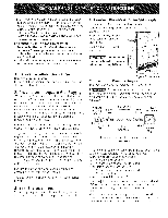
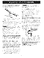
instructions in the Use and Care Guide. • Unlike the standard gas range, installed on the appliance. Do not make the connection too tight. The regulator is die cast. Overtightening may crack the regulator resulting in a gas leak and possible fire or explosion. Manual Shutoff Valve Flare Union GAS - Kenmore 7540 | Installation Instructions - Page 4
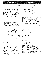
recommended to be installed with a Ground Fault Interrupt (GFI). Do not use an extension cord with this range. Manual Shutoff Valve Open position Figure 4 Once regulator is in place, open the shutoff valve in the gas supply line. Wait a few minutes for gas to move through the gas line. Check for - Kenmore 7540 | Installation Instructions - Page 5
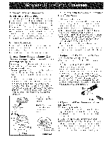
and switch on the electrical power and gas to the range. 8. Check Operation Refer to the Use and Care Guide packaged with the range for operating instructions and for care and cleaning of your range. Remove all packaging from the oven before testing. 8,1 Install Burner Bases and Burner Caps This - Kenmore 7540 | Installation Instructions - Page 6
When the igniter has reached a temperature sufficient to ignite gas, the electrically controlled oven valve will open and flame the range was adjusted for when it left the factory. Before You Call for Service Read the Before You Call Checklist and operating instructions in your Use and Care Guide. It - Kenmore 7540 | Installation Instructions - Page 7
spilled hot liquids or from the range itself. Refer to the instructions below for proper installation (Figure I 0). NOTE: If the range is ever moved to a different 10. These hold down brackets allow range to be freely pulled out from the wall for cleaning or servicing without the use of tools. I. - Kenmore 7540 | Installation Instructions - Page 8
puede ser instalado en el estado de Massachusetts pot un )lomero o ajustador de gas licenciado de Massachusett. Este aparato se debe instalar con un largo conector flexible de gas de tres (3) pies/36 pulgadas. Una wilvula manual de gas de tipo manija de forma de "T" se debe instalar en la linea del - Kenmore 7540 | Installation Instructions - Page 9
artefacto que use gas y genere calor, hay ciertas precauciones de seguridad que usted debe seguir. Estas seran encontradas en el Manual del Usuario, 16alo antivudco que se lesiones propordonan. Para comprobar personales. Instale el dispositivos antivueicoque se ha empacado junto con esta estufa - Kenmore 7540 | Installation Instructions - Page 10
es de die cast. El apretar demasiado puede agrietar el regulador dando por resultado una fuga de gas y un fuego o una explosion. Valvula de FLUJO DEL GAS Regulador cierre Uni6n _'_ manual Uni6n de presi6n _. A(boienrto)__,_ Boqtuilla Apagado (Off) ! _f-C_o\_n-e_ctor flexible J Boq!illa_ Tapa - Kenmore 7540 | Installation Instructions - Page 11
o 14" columna de agua). Aisle la estufa del sistema de tuberia del surninistro de gas cerrando su valvula de cierre manual durante cualquier prueba de presiOn del sistema de tuberia del suministro de gas prueba de presiOn iguala a o a menos de 1/2 psig (3,5 kPa o 14" columna de agua). La conversion - Kenmore 7540 | Installation Instructions - Page 12
La mudanza del aparato para reparaciones o lirnpieza Apague la corriente el_ctrica a la estufa a la fuente de poder principal, y apague la valvula de cierre manual de gas. Aseg0rese de que la estufa est_ fresca. Quite el cajOn de servicio (el caj6n calentador en algunos modelos) y abre la puerta del - Kenmore 7540 | Installation Instructions - Page 13
hacia el encendedor y tendra un resplandor de manera similar a una bombilla de luz. Cuando el encendedor a alcanzado una temperatura suficiente para encender el gas, la valvula del homo controlada el_ctricamente se abrira y el fuego aparecera en el quemador del homo. hay un lapso de tiempo de 30 - Kenmore 7540 | Installation Instructions - Page 14
presiOn a la cual fue ajustada la estufa en la f_ibrica. Antes de Llamar al Servicio Lea la secci6n Evite Llamadas de Servicio en su Manual del Usuario. Esto le podr_i ahorrar tiempo y gastos. Esta lista incluye ocurrencias comunes que no son el resultado de defectos de materiales o fabricaci6n de - Kenmore 7540 | Installation Instructions - Page 15
10. instrucciones para de instalaci6n del soporte antivueico Advertenda de seguridad importante Esta estufa debe ser asegurada al piso usando las platinas de anclaje y los tornillos suministrados. El no instalar apropiadamente los soportes antivueJcopuede Ilegar a permitir que la estufa se - Kenmore 7540 | Installation Instructions - Page 16
LUZ DE RORNO FAN MOTOR MOTOR DE VENTILAOOR CTRCUZTO DE PLANCHZA DE COCTNAR >_ R-1 >> w. W-1 Wd Wd FAN THERMOSTAT TERMOSTATO DE VENTILAOOR NOTE: SERVICE:IF REPLACEMENT OF TERMINALS BECOMES NECESSARY_COMPARABLE GAGE AND COMPARABLE TERMINALS MUST BE USED, NOTA: EN CASO QUE SEA NECESARIO BE
-
 1
1 -
 2
2 -
 3
3 -
 4
4 -
 5
5 -
 6
6 -
 7
7 -
8
-
9
-
10
-
11
-
12
-
13
-
14
-
15
-
16
 |
 |
@
iNSTALLATiON
AND
SERVICE
MUST
BE PERFORMED
BY
A QUALiFiED
iNSTALLER.
iMPORTANT:
SAVE FOR LOCAL
ELECTRICAL
iNSPECTOR'S
USE.
READ AND
SAVE THESE iNSTRUCTiONS
FOR FUTURE
REFERENCE.
If the information
in this manual
is not followed
exactly,
a fire
or explosion
may result
causing
property
damage,
personal
injury
or death.
FOR YOUR
SAFETY:
--
Do
not
store
or
use gasoline
or other
flammable
vapors
and
liquids
in
the
vicinity
of this
or any
other
appliance.
--
WHAT
TO
DO iF YOU
SMELL GAS:
*
Do not
try to light
any
appliance.
*
Do
not
touch
any
electrical
switch;
do
not
use any
phone
in
your
building.
*
Immediately
call your
gas supplier
from
a neighbor's
phone.
Follow
the
gas
supplier's
instructions.
*
If you
cannot
reach your
gas supplier,
call the
fire
department.
--
Installation
and
service
must
be performed
by a qualified
installer,
service
agency
or the
gas supplier.
Appliances
Installed
in
the
state
of
Massachusetts:
This
Appliance
can
only
be
installed
in the
state
of
Massachusetts
by a
Massachusetts
licensed
plumber
or gasfitter.
This
appliance
must
be
installed
with
a 3 foot
(36
in.)
long
flexible
gas connector.
A
"T"
handle
type
manual
gas
valve
must
be
installed
in the
gas supply
line
to
this
appliance.
Dimensions
and
Clearance
Provide
adequate
clearance
between
range
and
adjacent
combustible
surfaces.
2S
5/8"
38"
(65.1
cm)
47¾"
ii
(12
crn)
(91.4 cm)--_
Minimumclearanceon
Minimum
either side of range_
1_5" (12.7 cm)
above 36" (91.4 cm)
height if a wall is
installed _
13"
l
Minimum to
_(SScm)_"
18" cabinets on
Maximum depth
cm)either side of
for cabinets
i
range
above range top,
36
"
(91.4 cm)
36¼"
(92.1
cm)
Between
Cabinets
0"
Min,
Clearance
at rear of range
below
cooktop
from
the
back wall.
Figure
1
NOTE:
Wiring
diagram
for
this
appliance
is enclosed
in
this
booklet.
Printed in United States
P/N 318201759
(0605)
Rev. C
English -
pages 1-7
Espaflol -
paginas 8-15
Wiring
Diagram
- pages 16