Kenmore 7961 Installation Instructions
Kenmore 7961 - Pro 30 in. Gas Range Manual
 |
View all Kenmore 7961 manuals
Add to My Manuals
Save this manual to your list of manuals |
Kenmore 7961 manual content summary:
- Kenmore 7961 | Installation Instructions - Page 1
SERVICE MUST BE PERFORMED BY A QUALiFiED iNSTALLER. iMPORTANT: SAVE FOR LOCAL ELECTRICAL iNSPECTOR'S USE. READ AND SAVE THESE iNSTRUCTiONS FOR FUTURE REFERENCE. OBSERVE ALL GOVERNING CODES AND ORDINANCES. If the information in this manual power supply cord between the range and the wall. NOTE: 24 - Kenmore 7961 | Installation Instructions - Page 2
up excess spillage. Follow the cleaning instructions in the Use & Care Guide. Unlike the standard gas range, THiS COOKTOP IS NOT REMOVABLE. Do not attempt to remove the cooktop. Special Instructions for appliances installed in the State of Massachusetts: This appliance can only be installed in the - Kenmore 7961 | Installation Instructions - Page 3
or time delay fuse. Do not use an extension cord with this range. Grounding Instructions IMPORTANT Please read carefully. For personal safety, this appliance must be properly grounded. The power cord of this appliance is equipped with a 3prong (grounding) plug which mates with a standard 3prong - Kenmore 7961 | Installation Instructions - Page 4
turning on or shutting off gas to the appliance. Open the shutoff valve in the gas range, allow sufficient slack to pull the range outside the cutout for cleaning or servicing. NOTE: Do not allow the flexible conduit to get pinched between the wall and the range. Su__ugLgestgeads connection Manual - Kenmore 7961 | Installation Instructions - Page 5
in personal injury and property damage. Moving the Appliance for Servicing and Cleaning Turn off the range line fuse or circuit breakers at the main power source, and turn off the manual gas shut-off valve. Make sure the range is cold. Open the oven door. Lift the range at the front and slide it out - Kenmore 7961 | Installation Instructions - Page 6
be provided on both sides of the cooktop. Check Operation _rto the Use and Care Guide and the Electronic Oven Control Guide packaged with the range for operating instructions and for care and cleaning of your range. Remove all packaging from the oven before testing. 1. Burner Bases and Burner Caps - Kenmore 7961 | Installation Instructions - Page 7
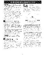
4.Adjustthe "LOW"Setting of Regular Burner (see figure 8) on the Surface Burner Valves (Figure 9): a. Push in and turn control to LITE until burner ignites. b. Quickly turn knob to LOWEST POSITION. c. If burner goes out, reset control to OFF. d. Remove the surface burner control knob and decorative - Kenmore 7961 | Installation Instructions - Page 8
Checklist and operating instructions in your Use and Care Guide. It may save you time and expense. The list includes common occurrences that are not the result of defective workmanship or materials in this appliance. Refer to your Use and Care Guide for Electrolux Service phone numbers, or call - Kenmore 7961 | Installation Instructions - Page 9
range. These parts are located in a plastic bag in the oven. 30" Range has one bracket. Failure to install the bracket wiil allow the range range itself. Follow the instructions below to install the anti-tip bracket. If range at back of the range. 2. The anti-tip bracket supports are attached to the - Kenmore 7961 | Installation Instructions - Page 10
NOTES: 10 - Kenmore 7961 | Installation Instructions - Page 11
/36"(91.4cm) Standard| 301/16" / 1%3 4t%3c t .x/ 4t00 c t , /t704c El diagrama del cableado de este modelo esta incluido en esta manual (vea la pagina 20) P/N318201776 (0808) Rev.A English- pages 1-10; Espaflol- p_iginas11-19 Impreso en los EstadosUnidos Diagramade la instalaci6nal_imbrica - Kenmore 7961 | Installation Instructions - Page 12
no debe de exceder 3 pies (36 pulgadas) de largo. Una valvula manual de tipo "T" debe de instalarse requiere aire fresco para la combustion apropiada de alimentacion de gas hacia este electrodomestico. base del homo u otra parte del aparato. SOlo utilizela para cubrir la comida cuando est_ - Kenmore 7961 | Installation Instructions - Page 13
. Nota Importante para el Consumidor Conserve estas instrucciones y el Manual del Usuario para referencia futura. Articuios Disponibles Opcionales: • Una Numero de Modelo y de Serie La placa de serie seencuentra en la parte trasera de la estufa Cuando haga pedidos de repuestos o solicite informaciOn - Kenmore 7961 | Installation Instructions - Page 14
de gas. Si se usan conectores flexibles asegOrese de que no est_n enroscados. La linea del suministro se debe equipar de una wilvula de cierre manual aprobada. Esta wilvula se debe Iocalizar en el mismo cuarto que la estufa y debe estar en una Iocalizaci0n que permita el f_icil acceso para abrir - Kenmore 7961 | Installation Instructions - Page 15
a la estufa a la fuente de poder principal, y cierre la wilvula manual de gas. Aseg0rese de que la estufa este frfa. Abra la puerta del su posicion final. Marque el piso pot los dos lados de la estufa. Si [a parte trasera de [a estufa no estar_ a ras con [a pared (la ubicacion del tomacorriente - Kenmore 7961 | Installation Instructions - Page 16
. Si no cumple con esta instruccion, usted podr,i lesionarse la espalda u otra parte de su cuerpo, 7.1 Nivelad6n de ia estufa 1. Coloque una parrilla del homo piso este nivelado. 7.2 Cornprobad6n del Fundonarniento Consulte el Manual del Usuario incluido con la estufa para instrucciones de - Kenmore 7961 | Installation Instructions - Page 17
C. Luego que el quemador se haya encendido, la perilla debe set girada fuera de la posicion LITE. Cada quemador tiene su encendedor individual. Controle las perillas separadamente hasta que todas las wilvulas hayan sido controladas. 4. Ajuste bajo ("LO"")para la v,ilvula de los quemadores de - Kenmore 7961 | Installation Instructions - Page 18
retirar el fondo del homo, retire los tomillos de ajuste del homo en la parte posteior del fondo del homo. jale hacia arriba, desenganche el frente del fondo del al Servicio Lea la secciOn Lista de control de averias en su Manual del Usuario. Esto le podr_i ahorrar tiempo y gastos. Esta lista - Kenmore 7961 | Installation Instructions - Page 19
1. Estufa de 30" Elsoporte antivuelco clebe de ser instalado en el lado derecho o_ izquierdo en la parte trasera de la unidad. 2. El soporte-base debe de fijarse al piso en la parte poste- patas posteriores se alineen con los soportes. 8. Despu6s de la instalaci6n, verifique visualmente que los - Kenmore 7961 | Installation Instructions - Page 20
TIQUETE ERRORES TOOOS LOS CABLES ANTES DE DESCONECTAR AL VOLVER A ENSAMBLAB LOS CABLES PUEDE CUANDO CAUSAR HAGA EL SERVIC[O A LOS CONTROLES. FALLAS U OPERACIONES PELZGROSAS. VERIFIQUE LA CORRECTA OPERAClON 9ESPUES DEL SERV[CIO, ATTENTION:COUPEZ L'ALIMEMTATION AVANT O'EFFECTUER
-
 1
1 -
 2
2 -
 3
3 -
 4
4 -
 5
5 -
 6
6 -
 7
7 -
8
-
9
-
10
-
11
-
12
-
13
-
14
-
15
-
16
-
17
-
18
-
19
-
20
 |
 |

iNSTALLATiON
AND
SERVICE MUST
BE
PERFORMED
BY A
QUALiFiED iNSTALLER.
iMPORTANT:
SAVE FOR
LOCAL
ELECTRICAL iNSPECTOR'S
USE.
READ
AND
SAVE THESE
iNSTRUCTiONS
FOR FUTURE
REFERENCE.
OBSERVE ALL GOVERNING
CODES AND
ORDINANCES.
If the
information
in
this
manual
is
not
followed
exactly,
a fire
or
explosion
may
result
causing
property
damage,
personal
injury
or
death.
FOR YOUR
SAFETY:
--
Do
not
store
or
use gasoline
or other
flammable
vapors
and
liquids
in
the
vicinity
of
this
or
any
other
appliance.
--
WHAT
TO
DO
IF
YOU
SMELL
GAS:
•
Do
not
try
to
light
any
appliance.
•
Do
not
touch
any
electrical
switch;
do
not
use any
phone
in
your
building.
•
Immediately
call
your
gas supplier
from
a neighbor's
phone.
Follow
the
gas
supplier's
instructions.
•
If you
cannot
reach
your
gas supplier,
call
the
fire
department.
--
Installation
and
service
must
be
performed
by
a qualified
installer,
service
agency
or
the
gas supplier.
Refer to your
serial plate for
applicable agency
certification
Note: For
app/iances
instafled in the
state of
Massachusetts
see page 2,
\
24"
Min.
Recommended
(61 cm Min.)
Grounded
24
1/2"
Max.
Wall
Outlet
(62.2 cm Max.)
Location
Do not pinch the power supply cord between the range
and the wall.
Do not seal the range to the side cabinets.
NOTE: 24" (61 cm) minimum
clearance between the
cooktop and the bottom of the cabinet when the bottom
of wood or metal cabinet is protected by not less than
1/4" (0.64 cm) flame retardant millboard
covered with
not less than No. 28 MSG sheet metal, 0.01 5" (0.4 mm)
stainless steel, 0.024"
(0.6 mm) aluminum, or 0.020"
(0.5 mm) copper.
30"
(76.2 cm) minimum
clearance when the cabinet is
unprotected.
Figure
1
A:HEiGHT
B:wiDTH
c:DEPTHTo
'
D:HEiGHTOF
E,DEPTHWITH
F,HEIGHTOF
G.
MINIMUM
,
FRONTOFRANGE
COOKTOP
DOOROPEN
COUNTERTOP
CUTOUTWIDTH
415/8"(105.7cm)Min.
297/8"
26 1/2"
353/4"(90.8cm)Min.
45 1/2"
36"(91.4cm)Standard
301/16"
425/8"(108.3cm)Max. (75.9cm)
(67.3cm)
363/4"(93.3cm)Max.
(115.6cm)
35 3/4" (90.8cm) Min.
(76.4cm)
Note:
Wiring
diagram
for this model
is enclosed
in this booklet
(see page
20).
P/N 318201776
(0808) Rev. A
Printed in United
States
English - pages 1-10; Espa_ol-
p_iginas 11-19
Wiring Diagram
- page 20