Kenmore 9961 Installation Instructions
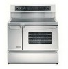
Kenmore 9961 - Elite 40 in. Electric Manual
 |
View all Kenmore 9961 manuals
Add to My Manuals
Save this manual to your list of manuals |
Kenmore 9961 manual content summary:
- Kenmore 9961 | Installation Instructions - Page 1
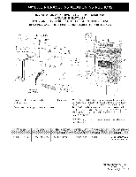
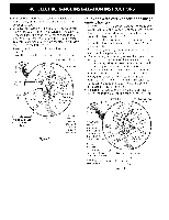
INSTRUCTIONS FOR FUTURE REFERENCE. 28 1/8" (71,4cm) _i with handleJ JI 1 D 24" Min. (61 cm Min.) Grounded 24 1/2" max. Wall Outlet (62.2 cm Max.) Do not pinch the power supply cord between the range 48 1/8"(122.24cm) 40 1/8"(101.9cm) 25 1/2"(64.8cm) 43 3/4"(111.1cm) 40 1/4"(102.2cm) 36 - Kenmore 9961 | Installation Instructions - Page 2
. Important Note to the Consumer Keep these instructions with your owner's guide for future reference. IMPORTANT SAFETY INSTRUCTIONS * Be sure your range is installed and grounded properly by a qualified installer or service technician. • This range must be electrically grounded in accordance with - Kenmore 9961 | Installation Instructions - Page 3
rated at 125/250 volts minimum, 40 amperes and marked for use with ranges should be used (see Figure 4). range cord kit is used, if the Installation Instructions are not followed, or if the strain relief bracket is discarded. Range Connection Opening Size Chart Refer to chart below for proper range - Kenmore 9961 | Installation Instructions - Page 4
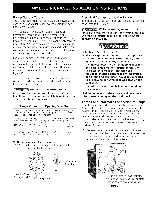
3 screws at the lower end of the rear wire cover, then raise the lower end of the rear wire cover (access cover) upward to expose range terminal connection block (see figure 2). 2. Remove the three loose nuts (after you removed the rubber band) on the terminal block using a 3/8" nut driver or - Kenmore 9961 | Installation Instructions - Page 5
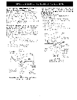
2 red wires together. White Wire (Neutra[) Cabmefrom Residence BRack Wires ] Box WEre (Neutra[) Green -(or Bare Copper) Wire Cable from Range UoL.o[isted Conduit Connector (or CSA misted) Figure S 3-Wire (Grounded Neutral) Electrical System (example: Junction Box) Where local codes DO NOT - Kenmore 9961 | Installation Instructions - Page 6
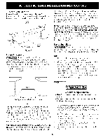
service cord is used, the wall receptacle should be located in accordance with the dimensions below. Center Line of Range the cabinet. If back of range Range Preparation I Follow instructions for the type of installation you have Figure 8 If range range to support range. 3. Firmly grasp the range - Kenmore 9961 | Installation Instructions - Page 7
for or making inquiries about your range, always be sure to include the model and serial numbers and a lot number or letter from the serial plate on your range. Before You Call for Service Read the Avoid Service Checklist and operating instructions in your Owner's Guide. It may save you time and - Kenmore 9961 | Installation Instructions - Page 8
on an open door or if a child climbs upon it. Serious injury might result from spilled hot liquids or from the range itself. Follow the instructions below to install the anti-tip brackets. If range is ever moved to a different location, the anti-tip brackets must also be moved and installed with the - Kenmore 9961 | Installation Instructions - Page 9
INSTALADOR CALIFICADO. IMPORTANTE: GUARDE ESTAS INSTRUCCIONES PARA USO DEL INSPECTOR LOCAL DE ELECTRICIDAD. LEA Y GUARDE ESTAS INSTRUCCIONES PARA REFERENCIA FUTURA. 40 1/8" Min. (101.9 cm) 28 1/8" (71,4cm) con tirador/ 2 t/2" Min. (6.4 cm M[n. Si hay uno pared, el lado izquierd 0 solamente (302 - Kenmore 9961 | Installation Instructions - Page 10
los c6digos y reglamentos pertinentes. 6. Deje estas instrucciones con el comprador. Nota Importante para el Consumidor Conserve estas instrucciones y el Manual del Usuario para referencia futura. IMPORTANTES • Asegt_rese de que el material que recubre las paredes alrededor de la estufa, pueda - Kenmore 9961 | Installation Instructions - Page 11
cable de cobre escudido no met_qlico) o un "juego de cordon electrico". Se usar_q solamente un juego de cordon electrico para 125/250 voltios minimo, 40 amperios minimo y marcado para uso con estufas. El juego de cordon electrico debe tenet 3 o 4 conductores. Para las casas sobre ruedas, las nuevas - Kenmore 9961 | Installation Instructions - Page 12
1. Quite los tres tornillos en la parte m_qs baja del panel trasero, luego levante la parte m_is baja del panel trasero (la cubierta de acceso) exponiendo el bloque de conexiones de los terminales de la estufa (vea Figura 2). 2. Quinte las tres tuercas desatadas (despues de remover la cinta de goma) - Kenmore 9961 | Installation Instructions - Page 13
Conexion electrica directa al cortacircuito, a la caja de fusibles o la caja de empalmes Si el aparato esta conectado directamente al cortacircuito, a la caja de fusibles o a la caja de empalmes, use un cable blindado flexible o no metalico recubierto de cobre (con alambre a tierra). Provee una - Kenmore 9961 | Installation Instructions - Page 14
una campana purificadora que se proyecta horizontalemente un minimo de 5" (12.7 cm) m_qs afuera de la parte inferior de los armarios. °l o Center Line of Range o I / Siga las instrucciones para el tipo de instalaci6n que usted tenga Figura 8 Si la estufa se va a instalar con un armario a ambos - Kenmore 9961 | Installation Instructions - Page 15
al Servicio Lea la secci6n Lista de control de aver[as en su Manual del Usuario. Esto le podr_q ahorrar tiempoy gastos. Esta lista incluye ocurrencias . Lea la garantia y la informaci6n sobre el servicio en su Manual del Usuario para obtener el n0mero de telefono gratuitoy la direcci6n delservicio - Kenmore 9961 | Installation Instructions - Page 16
Importante Advertencia de Seguridad Para reducir el riesgo de que la estufa se vuelque, es necesario asegurarla al piso instalando los soportes antivuelco y los tornillos suministrados con la estufa. Las piezas se encuentran en un saco de pkistico en el homo. Si no se instalan los soportes
-
 1
1 -
 2
2 -
 3
3 -
 4
4 -
 5
5 -
 6
6 -
 7
7 -
8
-
9
-
10
-
11
-
12
-
13
-
14
-
15
-
16
 |
 |

INSTALLATION
AND
SERVICE MUST
BE PERFORMED
BY
A
QUALIFIED
INSTALLER.
IMPORTANT:
SAVE FOR
LOCAL
ELECTRICAL INSPECTOR'S
USE.
READ AND
SAVE
THESE
INSTRUCTIONS
FOR FUTURE REFERENCE.
28 1/8"
(71,4cm)
_i
with
handleJ
J
I
1
24"
Min.
(61 cm
Min.)
Grounded
24
1/2"
max.
Wall
Outlet
(62.2
cm Max.)
D
Do not pinch the power supply cord between the range
and the wall.
Do not seal the range to the side cabinets.
**NOTE:
24" (61 cm) minimum
clearance between the
cooktop and the bottom of the cabinet when the bottom
of wood or metal cabinet is protected by not less than
1/4" (0.64 cm) flame retardant millboard
covered with
not lessthan No. 28 MSG sheet metal, 0.015"
(0.4 ram)
stainless steel, 0.024"
(0.6 ram) aluminum,
or 0.020"
(0.5 mm) copper.
30"
(76.2 cm) minimum
clearance when the cabinet is
unprotected.
iiiiiiiiiiiiiiiiiiiiiiiiiiiiiiiiiiiiiiiiiiiiiiiiiiiiiiiiiiiiiiiiiiiiiiiiiiiiiiiiiiiiiiiiiiiiiii+_+_+:
iiiiiiiiiiiiiiiiiiiiiiiiiiiiiiiiiiiiiiiiiiiiiiiiiiiiiiiiiiiiiiiiiiiiiiiiiiiiiiiiiiiiiiiiiiiiii_+i+_
' +i+i+i+i+i+i+i+i+i+i+i+i+i+i+i+i+i+i+i+i+i+i+i+i+i+iii_!+i_'ili
+_i_i_ii_i_i_i_i_i_i_i_i_i_i_i_i_i_i_i_i_i_i_i_i_i_i_i_!i_!_JJ+
i!i!i!i!i!i!i!i!i!i!i!i!i!i!i!i!i!i!i!i!!i_+!_!_+!_+!!_!_!_+!_3_+_+_i+_
_i_+_+_iiiiiiiiiiiiiiiiiiiiiiiii++iii_i_i_
481/8"(122.24cm)
40 1/8"(101.9cm)
251/2"(64.8cm)
433/4"(111.1cm)
40 1/4"(102.2cm)
36"(91.4cm) standard
35 3/8" (90 cm) min.
P/N 318201702
(0301) Rev.A
English - pages 1 - 8
Espa_ol - p_iginas 9 - 16