Kenwood DDX7029 User Manual 1
Kenwood DDX7029 Manual
 |
View all Kenwood DDX7029 manuals
Add to My Manuals
Save this manual to your list of manuals |
Kenwood DDX7029 manual content summary:
- Kenwood DDX7029 | User Manual 1 - Page 1
MONITOR WITH DVD RECEIVER DDX7029 INSTALLATION MANUAL © B54-4525-00/00 (EV/E2V) - Kenwood DDX7029 | User Manual 1 - Page 2
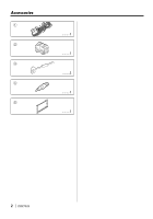
Accessories 1 2 3 4 5 ..........1 ..........1 ..........2 ..........1 ..........1 2 | DDX7029 - Kenwood DDX7029 | User Manual 1 - Page 3
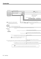
Installation Procedure 1. To prevent short circuits, remove the key from the ignition and disconnect the - terminal of the battery. 2. Make the proper input and output wire connections for each unit. 3. Connect the wire on the wiring harness. 4. Take Connector B on the wiring harness and connect it - Kenwood DDX7029 | User Manual 1 - Page 4
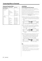
is grounded when either the telephone rings or during conversation. To connect the Kenwood navigation system, consult your navigation manual. Mute wire (Brown) Connect either to the power control terminal when using no connections are made, do not let the cable come out from the tab. 4 | DDX7029 - Kenwood DDX7029 | User Manual 1 - Page 5
Rear view Cooling fan FM/AM antenna input FUSE ( 10A ) Wiring harness (Accessory 1) REVERSE REMO.CONT MUTE ANT. CONT P CONT EXT.CONT English | 5 - Kenwood DDX7029 | User Manual 1 - Page 6
Connecting Wires to Terminals Connector Function Guide Pin Numbers for ISO Connectors External Power Connector A-4 A-5 A-6 A-7 A-8 Cable Colour Yellow Blue/White Orange/White Red Black Speaker Connector B-1 B-2 ) to a power source that can be turned on and off with the ignition key. 6 | DDX7029 - Kenwood DDX7029 | User Manual 1 - Page 7
System Connection USB device USB terminal (commercially available) Do not connect. Rear view AV OUT AV IN REAR VIEW CAMERA FRONT REAR ■ Audio/Visual Output • Visual output (Yellow) ■ Audio/Visual input • Visual input (Yellow) • Audio left input (White) • Audio right input (Red) ■ Rear View - Kenwood DDX7029 | User Manual 1 - Page 8
(Included in the Navigation System) Rear view Connection cable (Included in the Disc changer) Disc Changer etc. (Optional Accessory) TV ANTENNA INPUT TO MONITOR UNIT 8 | DDX7029 TV Tuner (Optional Accessory) Connection cable (Included in the TV tuner) - Kenwood DDX7029 | User Manual 1 - Page 9
Installation for Monitor/Player Unit Screw (M4X8) (commercially available) Firewall or metal support Self-tapping screw (commercially available) Metal mounting strap (commercially available) Bend the tabs of the mounting sleeve with a screwdriver or similar utensil and attach it - Kenwood DDX7029 | User Manual 1 - Page 10
from the catch pins on the removal tool. 5. Pull the unit all the way out with your hands, being careful not to drop it. 10 | DDX7029 - Kenwood DDX7029 | User Manual 1 - Page 11
English | 11 - Kenwood DDX7029 | User Manual 1 - Page 12
-
 1
1 -
 2
2 -
 3
3 -
 4
4 -
 5
5 -
 6
6 -
 7
7 -
8
-
9
-
10
-
11
-
12
 |
 |

©
B54-4525-00/00 (EV/E2V)
MONITOR WITH DVD RECEIVER
DDX7029
INSTALLATION MANUAL