Kenwood KDC-BT948HD Quick Start Guide - Page 14
Installation/Removing the Unit
 |
UPC - 019048193643
View all Kenwood KDC-BT948HD manuals
Add to My Manuals
Save this manual to your list of manuals |
Page 14 highlights
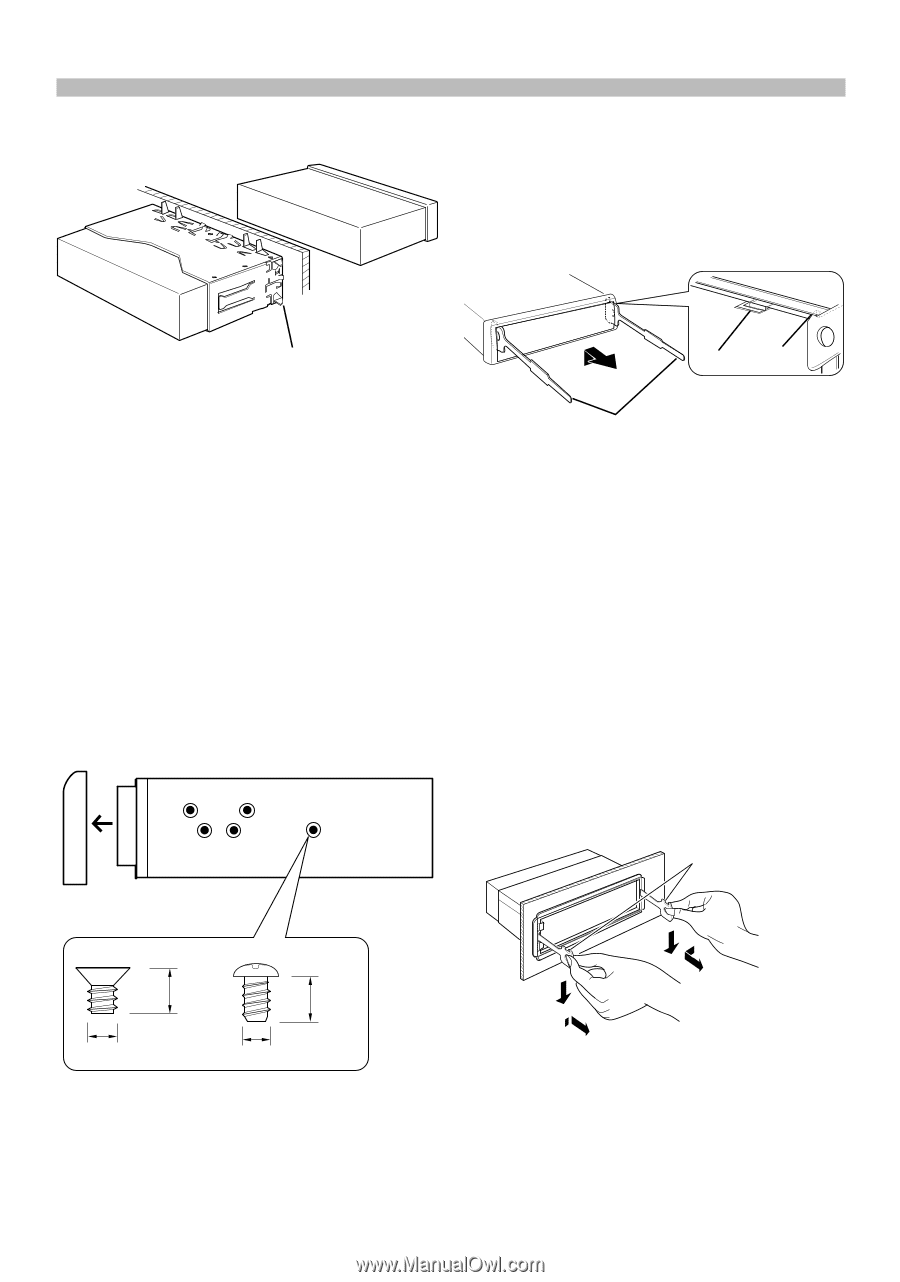
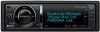
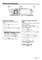
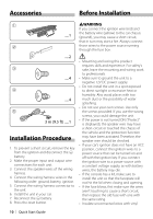
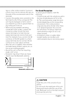
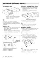
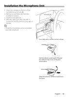
Installation/Removing the Unit non-Japanese cars Removing the hard rubber frame 1. Engage the catch pins on the removal tool and remove the two locks on the upper level. Lift up and pull the frame forward as shown in the figure. Bend the tabs of the mounting sleeve with a screwdriver or similar utensil and attach it in place. ⁄ • Make sure that the unit is installed securely in place. If the unit is unstable, it may malfunction (for example, the sound may skip). Japanese cars 1. Refer to the section and then remove the hard rubber frame. 2. Align the holes in the unit (two locations on each side) with the vehicle mounting bracket and secure the unit with the accessory screws. T N T/N NT T: Toyota cars N: Nissan cars 3 4 8 mm MAX. 8mm MAX. Lock Catch Removal tool (Accessory2) 2. When the upper level is removed, remove the lower two locations. ⁄ • The frame can be removed from the bottom side in the same manner. Removing the Unit 1. Refer to the section and then remove the hard rubber frame. 2. Remove the faceplate. 3. Insert the two removal tools deeply into the slots on each side, as shown. 4. Lower the removal tool toward the bottom, and pull out the unit halfway while pressing towards the inside. Accessory2 ø5mm ø5mm Accessory3...for Nissan car Accessory4...for Toyota car ¤ • Be careful to avoid injury from the catch pins on the removal tool. 5. Pull the unit all the way out with your hands, being careful not to drop it. 14 | Quick Start Guide
-
 1
1 -
2
-
3
-
4
-
5
-
6
-
7
-
8
-
 9
9 -
 10
10 -
 11
11 -
 12
12 -
 13
13 -
 14
14 -
 15
15 -
 16
16 -
 17
17 -
 18
18 -
 19
19 -
20
-
21
-
22
-
23
-
24
-
25
-
26
-
27
-
28
-
29
-
30
-
31
-
32
-
33
-
34
-
35
-
36
-
37
-
38
-
39
-
40
-
41
-
42
-
43
-
44
-
45
-
46
-
47
-
48
 |
 |