Kenwood KDC-MP208 Instruction Manual - Page 17
lJ-!8mm - installation
 |
UPC - 019048174413
View all Kenwood KDC-MP208 manuals
Add to My Manuals
Save this manual to your list of manuals |
Page 17 highlights
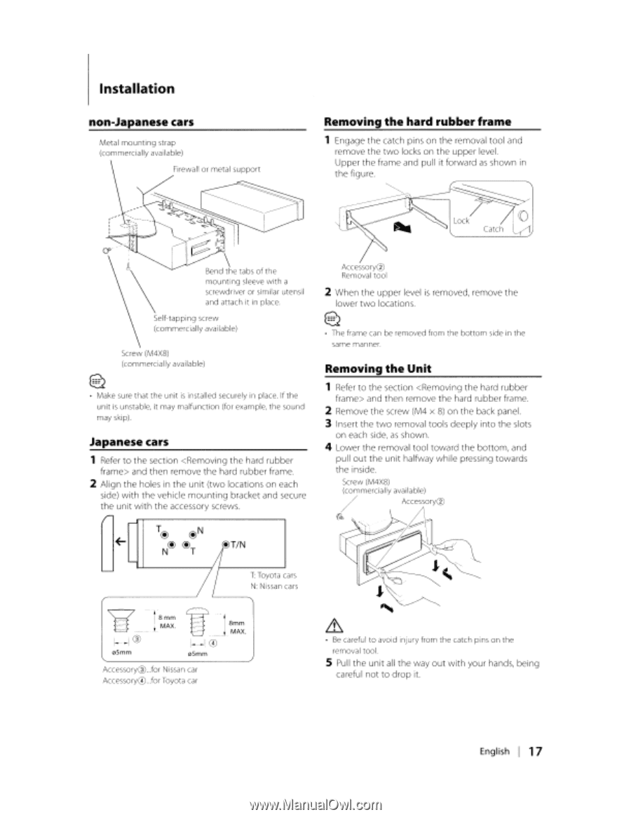
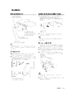
Installation non-Japanese cars Metal mounting strap (commercially available) Firewall or metal support Removing the hard rubber frame 1 Engage the catch pins on the removal tool and remove the two locks on the upper level. Upper the frame and pull it forward as shown in the figure. Self-tapping screw (commercially available) Screw (M4X8) (commercially available) 1~ :0 Make sure that the unit is installed securely in place. If the unit is unstable, it may malfunction (for example, the sound may skip) Japanese cars 1 Refer to the section and then remove the hard rubber frame. 2 Align the holes in the unit (two locations on each side) with the vehicle mounting bracket and secure the unit with the accessory screws. ,...- ~ '- T@ @N @@ NT I/@T/N /1 T: Toyota cars N: Nissan cars ~-- !8mm i_ MAX. 1--1 @ 05mm lJ-!8mm . __.1. MAX. I-IG) 05mm Accessory@ .for Nissan car AccessoryG) .for Toyota car Accessory0 Removal tool 2 When the upper level is removed, remove the lower two locations. 1~ :0 • The frame can be removed from the bottom side in the same manner. Removing the Unit 1 Refer to the section and then remove the hard rubber frame. 2 Remove the screw (M4 x 8) on the back panel. 3 Insert the two removal tools deeply into the slots on each side, as shown. 4 Lower the removal tool toward the bottom, and pullout the unit halfway while pressing towards the inside. Screw (M4X8) (commercially available) / Accessory0 ~ Lb. • Be careful to avoid injury from the catch pins on the removal tool. S Pull the unit all the way out with your hands, being careful not to drop it. English I 17
-
 1
1 -
2
-
3
-
4
-
5
-
6
-
7
-
8
-
9
-
10
-
11
-
 12
12 -
 13
13 -
 14
14 -
 15
15 -
 16
16 -
 17
17 -
 18
18 -
 19
19 -
 20
20 -
 21
21 -
 22
22 -
23
-
24
-
25
 |
 |