Kenwood KDC X493 Instruction Manual - Page 41
Accessories/ Installation Procedure - protect
 |
UPC - 019048182111
View all Kenwood KDC X493 manuals
Add to My Manuals
Save this manual to your list of manuals |
Page 41 highlights
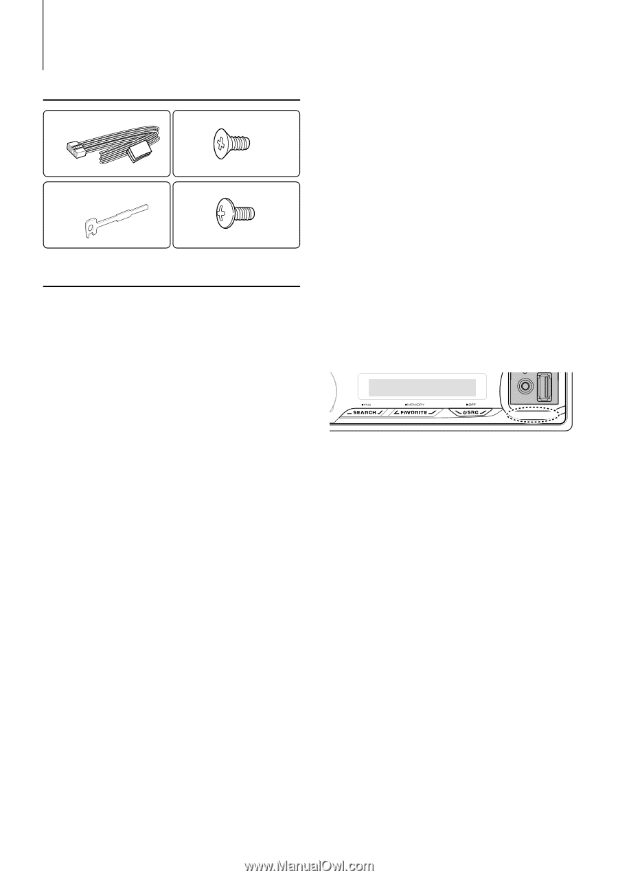
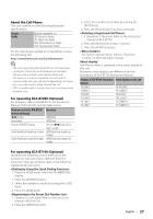
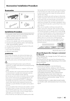
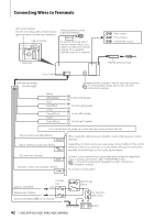
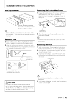
Accessories/ Installation Procedure Accessories 1 3 ..........1 ..........4 2 4 ..........2 ..........4 Installation Procedure 1. To prevent a short circuit, remove the key from the ignition and disconnect the - battery. 2. Make the proper input and output wire connections for each unit. 3. Connect the speaker wires of the wiring harness. 4. Connect the wiring harness wires in the following order: ground, battery, ignition. 5. Connect the wiring harness connector to the unit. 6. Install the unit in your car. 7. Reconnect the - battery. 8. Press the reset button. 2WARNING If you connect the ignition wire (red) and the battery wire (yellow) to the car chassis (ground), you may cause a short circuit, that in turn may start a fire. Always connect those wires to the power source running through the fuse box. ¤ • Mounting and wiring this product requires skills and experience. For safety's sake, leave the mounting and wiring work to professionals. • Make sure to ground the unit to a negative 12V DC power supply. • Do not install the unit in a spot exposed to direct sunlight or excessive heat or humidity. Also avoid places with too much dust or the possibility of water splashing. • Do not use your own screws. Use only the screws provided. If you use the wrong screws, you could damage the unit. • If the power is not turned ON ("PROTECT" is displayed), the speaker wire may have a short-circuit or touched the chassis of the vehicle and the protection function may have been activated. Therefore, the speaker wire should be checked. • If your car's ignition does not have an ACC position, connect the ignition wires to a power source that can be turned on and off with the ignition key. If you connect the ignition wire to a power source with a constant voltage supply, as with battery wires, the battery may die. • If the console has a lid, make sure to install the unit so that the faceplate will not hit the lid when closing and opening. • If the fuse blows, first make sure the wires aren't touching to cause a short circuit, then replace the old fuse with one with the same rating. • Insulate unconnected wires with vinyl tape or other similar material. To prevent a short circuit, do not remove the caps on the ends of the unconnected wires or the terminals. • Connect the speaker wires correctly to the terminals to which they correspond. The unit may be damaged or fail to work if you share the - wires or ground them to any metal part in the car. • When only two speakers are being connected to the system, connect the connectors either to both the front output terminals or to both the rear output terminals (do not mix front and rear). For example, if you connect the + connector of the left speaker to a front output terminal, do not connect the - connector to a rear output terminal. • After the unit is installed, check whether the brake lamps, blinkers, wipers, etc. on the car are working properly. • Mount the unit so that the mounting angle is 30° or less. • Reception may drop if there are metal objects near the Bluetooth antenna. Bluetooth antenna unit About CD players/disc changers connected to this unit If the CD player/ disc changer has the "O-N" switch, set it to the "N" position. The functions you can use and the information that can be displayed may differ depending on the models being connected. For Good Reception To assure good reception, note the following: • Communicate with the cell-phone within the line- of-sight distance of 10 m (30 ft). The communication range becomes shorter depending on the surrounding environment. The communication range also becomes shorter when there is an obstacle between this unit and the cell-phone. The above maximum communication range (10 m) is not always assured. • A broadcast station or walkie-talkie located nearby can interfere with communication due to too strong signal. English | 41
-
 1
1 -
2
-
3
-
4
-
5
-
6
-
7
-
8
-
9
-
10
-
11
-
12
-
13
-
14
-
15
-
16
-
17
-
18
-
19
-
20
-
21
-
22
-
23
-
24
-
25
-
26
-
27
-
28
-
29
-
30
-
31
-
32
-
33
-
34
-
35
-
 36
36 -
 37
37 -
 38
38 -
 39
39 -
 40
40 -
 41
41 -
 42
42 -
 43
43 -
 44
44 -
 45
45 -
 46
46 -
47
-
48
-
49
-
50
-
51
-
52
-
53
-
54
-
55
-
56
-
57
-
58
-
59
-
60
-
61
-
62
-
63
-
64
-
65
-
66
-
67
-
68
-
69
-
70
-
71
-
72
-
73
-
74
-
75
-
76
-
77
-
78
-
79
-
80
-
81
-
82
-
83
-
84
-
85
-
86
-
87
-
88
-
89
-
90
-
91
-
92
-
93
-
94
-
95
-
96
-
97
-
98
-
99
-
100
-
101
-
102
-
103
-
104
-
105
-
106
-
107
-
108
-
109
-
110
-
111
-
112
-
113
-
114
-
115
-
116
-
117
-
118
-
119
-
120
-
121
-
122
-
123
-
124
-
125
-
126
-
127
-
128
-
129
-
130
-
131
-
132
-
133
-
134
-
135
-
136
-
137
-
138
-
139
-
140
 |
 |