Kenwood KES-3 User Manual
Kenwood KES-3 Manual
 |
View all Kenwood KES-3 manuals
Add to My Manuals
Save this manual to your list of manuals |
Kenwood KES-3 manual content summary:
- Kenwood KES-3 | User Manual - Page 1
included in the box. Self-tapping screw 2 Flat washer 2 Instruction Manual 1 MAINTENANCE Do not use any type of abrasive pad, thinner le support avec les deux vis taraudeuses. (voir Fig. 2). 6 Fixez le haut-parleur au support de montage, mais sans trop serrer. 7 Le support de montage - Kenwood KES-3 | User Manual - Page 2
confezione e verificare che siano presenti tutti gli articoli riportati nella tabella sottostante. Vite autofilettante 2 Rondella piatta 2 Manuale di istruzioni 1 MANUTENZIONE Non utilizzare spugne abrasive, acqua ragia, benzene o qualunque sostanza che possa arrecare danni all'unità. Detergere
-
 1
1 -
 2
2
 |
 |
KES-3
(
S
)
EXTERNAL SPEAKER
INSTRUCTION MANUAL
© B62-1631-18 (M)
HAUT PARLEUR EXTERNE
MODE D’EMPLOI
ALTAVOZ EXTERIOR
MANUAL DE INSTRUCCIONES
Thank you for purchasing this External
Speaker.
UNPACKING
Unpack your new Speaker carefully
and confirm that the accessories listed
below are included in the box.
Self-tapping screw
.....................................
2
Flat washer
................................................
2
Instruction Manual
.....................................
1
MAINTENANCE
Do not use any type of abrasive pad,
thinner, benzene, or any substances
which may damage the unit.
Wipe the front panel and other exterior
surfaces of the unit with a soft dry cloth
or a soft cloth lightly moistened with
water.
SPECIFICATIONS
Speaker size:
50 mm x 90 mm
1.97 in. x
3.54 in.
Maximum input power:
5 W
Impedance:
4
Frequency response:
300 Hz to 9 kHz
Plug:
3.5 mm
Dimension (W x H x D):
114 mm x 66 mm
x 55 mm
4.49 in. x 2.60 in.
x 2.17 in.
Weight:
12.3 oz (350
g
)
Note:
Ratings are subject to change without
notice due to advancement in technology.
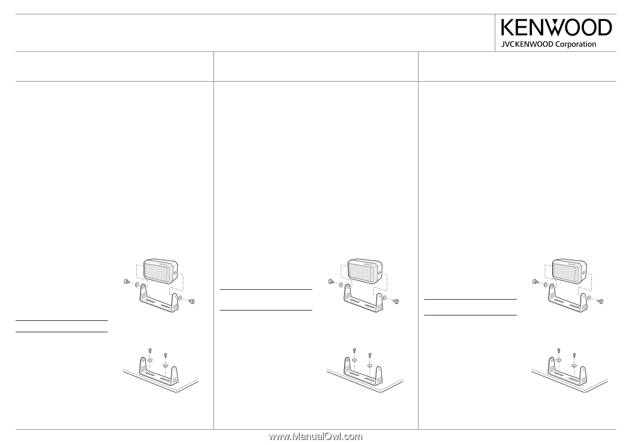
INSTALLATION INSTRUCTIONS
1
Select the desired mounting position.
2
Loosen the two mounting screws
and remove the bracket from the
speaker (refer to Fig. 1).
3
Use the bracket as a template
to locate the holes and mark the
position of the two mounting screws.
4
Drill the two holes, using a 0.12 in.
(3 mm) drill for self-tapping screws.
5
Secure the bracket with the two
supplied self-tapping screws
(refer to Fig. 2).
6
Attach the speaker to the bracket,
loosely.
7
The angle of the bracket, may be
adjusted to any of several possible
angles.
Select the desired angle.
8
Hold the speaker in position and
tighten the mounting screws.
Fig. 1
Fig. 2
Merci d’avoir acheté ce haut-parleur
externe.
DÉBALLAGE
Déballez votre nouveau haut-parleur avec
soin et vérifiez la présence des accessoires
suivants.
Vis taraudeuse
...................................................
2
Rondelle plate
....................................................
2
Mode d’emploi
...................................................
1
ENTRETIEN
N’utilisez aucun tampon abrasif, diluant,
benzène ou autre substance pouvant
endommager l’appareil.
Essuyez le panneau avant et les autres
surfaces extérieures de l’appareil au moyen
d’un chiffon doux et sec ou d’un chiffon
doux légèrement humecté d’eau.
FICHE TECHNIQUE
Dimensions du haut-parleur:
50 mm x 90 mm
Puissance maximale
d’entrée:
5 W
Impédance:
4
Réponse en fréquence:
300 Hz à 9 kHz
Fiche:
3,5 mm
Dimensions (L x H x P):
114 mm x 66 mm
x 55 mm
Poids:
350
g
Remarque:
En raison des nouveaux
développements technologiques, les
caractéristiques nominales sont sujettes à
changement sans préavis.
INSTRUCTIONS D’INSTALLATION
1
Choisissez la position de montage
désirée.
2
Desserrez les deux vis de montage et
enlevez le support du haut-parleur (voir
Fig. 1).
3
Utilisez le support comme gabarit
pour positionner les trous et marquer
l’emplacement des deux vis de montage.
4
Percez les deux trous pour les vis
taraudeuses à l’aide d’un foret de 3 mm.
5
Assujettissez le support avec les deux
vis taraudeuses. (voir Fig. 2).
6
Fixez le haut-parleur au support de
montage, mais sans trop serrer.
7
Le support de montage peut être réglé
à différents angles. Choisissez celui qui
vous convient le mieux.
8
Maintenez le haut-parleur en place et
serrez les vis de montage.
Fig. 1
Fig. 2
Le agradecemos la adquisición de este
Altavoz Exterior.
DESEMBALAJE
Desembale su nuevo Altavoz
cuidadosamente y confirme que los
siguientes accesorios estén incluidos en la
caja.
Tornillo de rosca cortante
..................................
2
Arandela plana
..................................................
2
Manual de Instrucciones
....................................
1
MANTENIMIENTO
No use ningún tipo de esponja abrasiva,
solvente, bencina o sustancia alguna que
pueda dañar la unidad.
Limpie el panel delantero y otras superficies
exteriores de la unidad con un trapo seco o
humedecido con agua.
ESPECIFICACIONES
Tamaño del altavoz:
50 mm x 90 mm
Potencia de
entrada máxima:
5 W
Impedancia:
4
Respuesta de frecuencia:
300 Hz a 9 kHz
Enchufe:
3,5 mm
Dimensiones
(ancho x altura
x profundidad):
114 mm x 66 mm
x 55 mm
Peso:
350
g
Nota:
Las clasificaciones se encuentran
sujetas a cambios sin previo aviso debido a
los avances de la tecnología.
INSTRUCCIONES DE INSTALACIÓN
1
Seleccione la posición de montaje
deseada.
2
Afloje los dos tornillos de montaje y
quite el soporte del altavoz (consulte la
Fig. 1).
3
Use el soporte como plantilla para
ubicar los agujeros y marcar la posición
de los tornillos de montaje.
4
Perfore los dos agujeros utilizando una
barrena de 0,12 pulgada (3 mm) para
los tornillos de rosca cortante.
5
Asegure el soporte con dos tornillos de
rosca cortante (Véase Fig. 2).
6
Atornille el altavoz al soporte, sin ajustar.
7
La inclinación del soporte se puede
ajustar a diferentes ángulos. Seleccione
la inclinación deseada.
8
Sostenga el altavoz en esa posición y
ajuste los tornillos de montaje.
Fig. 1
Fig. 2