Kyocera ECOSYS FS-4100DN PRESCRIBE Commands Technical Reference Manual - Rev. - Page 210
Plot Coordinates bit 0, Response to SP Instruction bit 1, Automatic Plot Coordinate Mode bit 2
 |
View all Kyocera ECOSYS FS-4100DN manuals
Add to My Manuals
Save this manual to your list of manuals |
Page 210 highlights
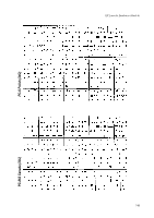
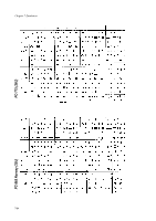
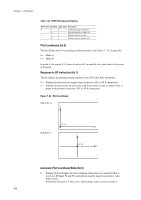
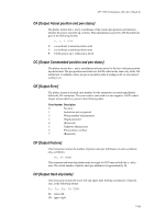
Chapter 7 Emulation Table 7.28. FRPO G0 Command Options Bit Position Bit Value Logic Value Description 4 0 0 Landscape page orientation 16 1 Page orientation to FRPO C1 5 0 0 Default cursor at top left 32 1 Default cursor at bottom left Plot Coordinates (bit 0) This bit defines one of two plotting coordinate modes. (See Figure 7. 29. on page 98.) 0 = Mode A 1 = Mode B In mode A, the origin (0, 0) starts at bottom left. In mode B, the origin starts at the center of the page. Response to SP Instruction (bit 1) This bit defines the printing system response to the SP (Select Pen) instruction. 0 = Printing System feeds out a page when it receives a SP; or SP 0; instruction. 1 = Printing System returns the pen to the stall from which it came, in other words, it prints nothing when it receives a SP; or SP 0; instruction. Figure 7. 29. Plot Coordinates Mode A (G0, 0;) Mode B (G0, 1;) Automatic Plot Coordinate Mode (bit 2) 0 = Printing System changes the plot coordinate from mode A to mode B when it receives a IP (Input P1 and P2) instruction using the negative parameter value. When the IN (INitialize) instruction is later given, the printing system reverts to mode A. 7-98
-
 1
1 -
2
-
3
-
4
-
5
-
6
-
7
-
8
-
9
-
10
-
11
-
12
-
13
-
14
-
15
-
16
-
17
-
18
-
19
-
20
-
21
-
22
-
23
-
24
-
25
-
26
-
27
-
28
-
29
-
30
-
31
-
32
-
33
-
34
-
35
-
36
-
37
-
38
-
39
-
40
-
41
-
42
-
43
-
44
-
45
-
46
-
47
-
48
-
49
-
50
-
51
-
52
-
53
-
54
-
55
-
56
-
57
-
58
-
59
-
60
-
61
-
62
-
63
-
64
-
65
-
66
-
67
-
68
-
69
-
70
-
71
-
72
-
73
-
74
-
75
-
76
-
77
-
78
-
79
-
80
-
81
-
82
-
83
-
84
-
85
-
86
-
87
-
88
-
89
-
90
-
91
-
92
-
93
-
94
-
95
-
96
-
97
-
98
-
99
-
100
-
101
-
102
-
103
-
104
-
105
-
106
-
107
-
108
-
109
-
110
-
111
-
112
-
113
-
114
-
115
-
116
-
117
-
118
-
119
-
120
-
121
-
122
-
123
-
124
-
125
-
126
-
127
-
128
-
129
-
130
-
131
-
132
-
133
-
134
-
135
-
136
-
137
-
138
-
139
-
140
-
141
-
142
-
143
-
144
-
145
-
146
-
147
-
148
-
149
-
150
-
151
-
152
-
153
-
154
-
155
-
156
-
157
-
158
-
159
-
160
-
161
-
162
-
163
-
164
-
165
-
166
-
167
-
168
-
169
-
170
-
171
-
172
-
173
-
174
-
175
-
176
-
177
-
178
-
179
-
180
-
181
-
182
-
183
-
184
-
185
-
186
-
187
-
188
-
189
-
190
-
191
-
192
-
193
-
194
-
195
-
196
-
197
-
198
-
199
-
200
-
201
-
202
-
203
-
204
-
 205
205 -
 206
206 -
 207
207 -
 208
208 -
 209
209 -
 210
210 -
 211
211 -
 212
212 -
 213
213 -
 214
214 -
 215
215 -
216
-
217
-
218
-
219
-
220
-
221
-
222
-
223
-
224
-
225
-
226
-
227
-
228
-
229
-
230
-
231
-
232
-
233
-
234
-
235
-
236
-
237
-
238
-
239
-
240
-
241
-
242
-
243
-
244
-
245
-
246
-
247
-
248
-
249
-
250
-
251
-
252
-
253
-
254
-
255
-
256
-
257
-
258
-
259
-
260
 |
 |