Kyocera ECOSYS FS-4100DN PRESCRIBE Commands Technical Reference Manual - Rev. - Page 54
Clipping Rectangle
 |
View all Kyocera ECOSYS FS-4100DN manuals
Add to My Manuals
Save this manual to your list of manuals |
Page 54 highlights
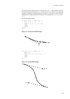
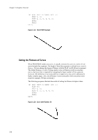
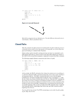
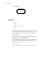
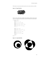
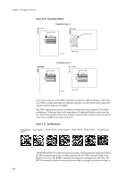
Chapter 2 Graphics Tutorial With 1 specified for the rule parameter of FILL, the method for determining whether a point is inside the path involves drawing a ray from that point in any direction and counting the number of times the ray crosses segments of the path. The point is said to be inside the path if the result is an odd number; if the result is an even number, the point is said to be outside the path. The non-zero winding rule also draws a ray from a point in any direction to determine whether or not that point is inside the path and examines the points where a segment of the path crosses the ray. However, it then starts counting from zero and adds one each time a segment in the path crosses the ray from left to right; and subtracts one each time a segment in the path crosses the ray from right to left. If the result of counting all the crossings is zero, the point is said to be outside; otherwise the point is said to be inside the path. After filling the current path, the FILL command clears the path in the same manner as NEWP. Clipping Rectangle Up to this point, we have discussed graphics objects to be drawn or stroked or filled as paths. However, another PRESCRIBE command can be used to define a clipping template for clipping texts, paths, and raster graphics. For this purpose, the CLPR (CLiP Rectangular region) command is provided to define the rectangular region for clipping paths. When the printing system is turned on or reset with PRESCRIBE's RES command, the clipping rectangle is identical to the printable limits of the page. Subsequently, executing the CLPR command reduces the clipping rectangle to the intersection of the objects on the page and the rectangle defined by CLPR. The following is an example of CLPR. !R! RES; UNIT C; NEWP; SPD 1; PMRA 6, 9, 3, 0; PARC 6, 9, 3, 0, 360; CLPR 3, 6, 9, 12; STRK; EXIT; In this example, lines 1 through 5 draw a circle with an extra line thickness at the coordinates defined by the PMRA command. The CLPR command on line 6 constructs a rectangle with its left-upper corner positioned at coordinates 3, 6 and its right-bottom corner positioned at coordinates 9, 12 (both measured from the top and left edge limits of the page). As with the rectangular area clipping, those parts of the circle that lie outside of the clipping rectangle are erased when the path is stroked, producing the result as shown in the figure on the next page. The rectangle defined by CLPR does not clip the graphics objects which are drawn by the standard mode graphics commands. 2-32
-
 1
1 -
2
-
3
-
4
-
5
-
6
-
7
-
8
-
9
-
10
-
11
-
12
-
13
-
14
-
15
-
16
-
17
-
18
-
19
-
20
-
21
-
22
-
23
-
24
-
25
-
26
-
27
-
28
-
29
-
30
-
31
-
32
-
33
-
34
-
35
-
36
-
37
-
38
-
39
-
40
-
41
-
42
-
43
-
44
-
45
-
46
-
47
-
48
-
 49
49 -
 50
50 -
 51
51 -
 52
52 -
 53
53 -
 54
54 -
 55
55 -
 56
56 -
 57
57 -
 58
58 -
 59
59 -
60
-
61
-
62
-
63
-
64
-
65
-
66
-
67
-
68
-
69
-
70
-
71
-
72
-
73
-
74
-
75
-
76
-
77
-
78
-
79
-
80
-
81
-
82
-
83
-
84
-
85
-
86
-
87
-
88
-
89
-
90
-
91
-
92
-
93
-
94
-
95
-
96
-
97
-
98
-
99
-
100
-
101
-
102
-
103
-
104
-
105
-
106
-
107
-
108
-
109
-
110
-
111
-
112
-
113
-
114
-
115
-
116
-
117
-
118
-
119
-
120
-
121
-
122
-
123
-
124
-
125
-
126
-
127
-
128
-
129
-
130
-
131
-
132
-
133
-
134
-
135
-
136
-
137
-
138
-
139
-
140
-
141
-
142
-
143
-
144
-
145
-
146
-
147
-
148
-
149
-
150
-
151
-
152
-
153
-
154
-
155
-
156
-
157
-
158
-
159
-
160
-
161
-
162
-
163
-
164
-
165
-
166
-
167
-
168
-
169
-
170
-
171
-
172
-
173
-
174
-
175
-
176
-
177
-
178
-
179
-
180
-
181
-
182
-
183
-
184
-
185
-
186
-
187
-
188
-
189
-
190
-
191
-
192
-
193
-
194
-
195
-
196
-
197
-
198
-
199
-
200
-
201
-
202
-
203
-
204
-
205
-
206
-
207
-
208
-
209
-
210
-
211
-
212
-
213
-
214
-
215
-
216
-
217
-
218
-
219
-
220
-
221
-
222
-
223
-
224
-
225
-
226
-
227
-
228
-
229
-
230
-
231
-
232
-
233
-
234
-
235
-
236
-
237
-
238
-
239
-
240
-
241
-
242
-
243
-
244
-
245
-
246
-
247
-
248
-
249
-
250
-
251
-
252
-
253
-
254
-
255
-
256
-
257
-
258
-
259
-
260
 |
 |