Kyocera ECOSYS FS-4100DN PRESCRIBE Commands Technical Reference Manual - Rev. - Page 61
Saving and Restoring the Graphics State
 |
View all Kyocera ECOSYS FS-4100DN manuals
Add to My Manuals
Save this manual to your list of manuals |
Page 61 highlights
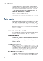
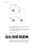
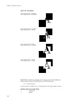
Raster Graphics 3 Transparent Transparent 4 Transparent Opaque 5 Opaque Transparent 6 Opaque Opaque With operation modes 1 and 2, the SIMG command addresses the transparency of the source image only. For operation mode 1, the white pixels of the source image do not overlay on the destination. For example, you cannot pattern a character. With operation mode 2, the SIMG command applies the white pixels of the source image onto the destination directly. The following program example illustrates use of the SIMG command. Try changing the value specified for SIMG on line 3 and see the effect on the result (the figure on the previous page). !R! RES; UNIT C; NEWP; SIMG 3; CMNT Try changing this value; PMZP 5, 15; PMRP 2, 2; PDRP 0, -2, 2, 0, 0, 2, -2, 0; PDRP -2, 0, 0, 2, 2, 0, 0, -2; FILL 1; SFNT 'TimesNewRoman', 90; PMRP -1.2, 1; GPAT .6; TEXT 'A'; FILL 1; PAGE; EXIT; Saving and Restoring the Graphics State The graphics state consists of a variety of items that affect how images are rendered on the page. The graphics state contains various information related to path mode graphics and raster mode graphics. Items included in the graphics state include the following: • Current path and cursor position (if defined) • Current pen diameter (line width) • Current line join type • Current line cap type • Current miter limit • Current dash pattern • Current flatness • Current fill pattern (16 × 16 dots) • Current clipping rectangle • Current raster resolution • Current image model While working with graphics, there often are occasions when it is useful to save the graphics state, then later to restore it. One such situation occurs when a path must be used for both stroking and filling. 2-39
-
 1
1 -
2
-
3
-
4
-
5
-
6
-
7
-
8
-
9
-
10
-
11
-
12
-
13
-
14
-
15
-
16
-
17
-
18
-
19
-
20
-
21
-
22
-
23
-
24
-
25
-
26
-
27
-
28
-
29
-
30
-
31
-
32
-
33
-
34
-
35
-
36
-
37
-
38
-
39
-
40
-
41
-
42
-
43
-
44
-
45
-
46
-
47
-
48
-
49
-
50
-
51
-
52
-
53
-
54
-
55
-
 56
56 -
 57
57 -
 58
58 -
 59
59 -
 60
60 -
 61
61 -
 62
62 -
 63
63 -
 64
64 -
 65
65 -
 66
66 -
67
-
68
-
69
-
70
-
71
-
72
-
73
-
74
-
75
-
76
-
77
-
78
-
79
-
80
-
81
-
82
-
83
-
84
-
85
-
86
-
87
-
88
-
89
-
90
-
91
-
92
-
93
-
94
-
95
-
96
-
97
-
98
-
99
-
100
-
101
-
102
-
103
-
104
-
105
-
106
-
107
-
108
-
109
-
110
-
111
-
112
-
113
-
114
-
115
-
116
-
117
-
118
-
119
-
120
-
121
-
122
-
123
-
124
-
125
-
126
-
127
-
128
-
129
-
130
-
131
-
132
-
133
-
134
-
135
-
136
-
137
-
138
-
139
-
140
-
141
-
142
-
143
-
144
-
145
-
146
-
147
-
148
-
149
-
150
-
151
-
152
-
153
-
154
-
155
-
156
-
157
-
158
-
159
-
160
-
161
-
162
-
163
-
164
-
165
-
166
-
167
-
168
-
169
-
170
-
171
-
172
-
173
-
174
-
175
-
176
-
177
-
178
-
179
-
180
-
181
-
182
-
183
-
184
-
185
-
186
-
187
-
188
-
189
-
190
-
191
-
192
-
193
-
194
-
195
-
196
-
197
-
198
-
199
-
200
-
201
-
202
-
203
-
204
-
205
-
206
-
207
-
208
-
209
-
210
-
211
-
212
-
213
-
214
-
215
-
216
-
217
-
218
-
219
-
220
-
221
-
222
-
223
-
224
-
225
-
226
-
227
-
228
-
229
-
230
-
231
-
232
-
233
-
234
-
235
-
236
-
237
-
238
-
239
-
240
-
241
-
242
-
243
-
244
-
245
-
246
-
247
-
248
-
249
-
250
-
251
-
252
-
253
-
254
-
255
-
256
-
257
-
258
-
259
-
260
 |
 |