Kyocera FS-1050 Service Manual
Kyocera FS-1050 - B/W Laser Printer Manual
 |
View all Kyocera FS-1050 manuals
Add to My Manuals
Save this manual to your list of manuals |
Kyocera FS-1050 manual content summary:
- Kyocera FS-1050 | Service Manual - Page 1
Laser printer SERVICE MANUAL Published in Dec. '01 - Kyocera FS-1050 | Service Manual - Page 2
Revision history Version 1.0 Date 5-Dec-2001 Replaced pages Remarks - Kyocera FS-1050 | Service Manual - Page 3
personnel to ensure the safety of their customers, their machines as well as themselves during maintenance activities. Service personnel are advised to read this booklet carefully to familiarize themselves with the warnings and precautions described here before engaging in maintenance activities - Kyocera FS-1050 | Service Manual - Page 4
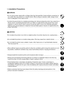
used to protect our service personnel and customers from indicates a warning including danger and caution. The specific point of attention is shown inside the symbol. General high temperature. indicates a prohibited action. The specific prohibition is shown inside the symbol. General prohibited - Kyocera FS-1050 | Service Manual - Page 5
on printers so equipped. Failure to do this may cause the printer to move unexpectedly or topple, leading to injury • Avoid inhaling toner or developer excessively. Protect the eyes. If toner or developer always follow the safety warnings and precautions in the printer's instruction handbook... - Kyocera FS-1050 | Service Manual - Page 6
Always use parts having the correct specifications Always use the thermostat or thermal fuse specified in the service manual or other • Never attempt to disassemble the optical unit in machines using lasers. Leaking laser light may damage eyesight...• Handle the charger sections with care. They - Kyocera FS-1050 | Service Manual - Page 7
always check that all the parts, screws, connectors and wires on the machine according to the instruction handbook are clean and not peeling. toner or toner bottles in fire. Toner may cause sparks when exposed directly to fire in a furnace, etc...• Should smoke be seen coming from the printer - Kyocera FS-1050 | Service Manual - Page 8
Printer specifications ...1-3 1-2 Names of parts ...1-6 1-3 Safety information ...1-7 1-4 Environmental requirements ...1-10 1-5 About the toner container ...1-14 Chapter 2 2-1 Unpacking ...2-3 2-2 Installing the printer instructions ...5-3 5-2 Disassembly ...5-4 Chapter 6 6-1 Troubleshooting - Kyocera FS-1050 | Service Manual - Page 9
Chapter 1 P r o d u c t I n f o r m a t i o n - Kyocera FS-1050 | Service Manual - Page 10
Chapter 1 Contents 1-1 Printer specifications ...1-3 1-1-1 Specifications ...1-3 (1) Engine ...1-3 (2) Controller ...1-4 (3) Weight and dimensions ...1-4 (4) Power requirements ...1-5 (5) Environmental requirements 1-5 1-2 Names of parts ...1-6 1-2-1 Name of parts ...1-6 1-3 Safety information - Kyocera FS-1050 | Service Manual - Page 11
first Mono component developer Visible laser Scorotron positive charging Negative charger roller Curvature separation Blade Eraser lamp (LED array) Heat roller and press roller Plain paper: Legal to A5 Cassette: 250 sheets, MP tray: 50 sheets Face-up: 30 sheets, Face-down: 150 sheets FS-1050 1-3 - Kyocera FS-1050 | Service Manual - Page 12
modes PCL6, Diablo 630, IBM proprinter X24E, Epson LQ850, Line printer, KPDL2 (3) Weight and dimensions Item Specification Item S Main unit (excl. protrusions) Width: Height: Depth: Weight: 378 mm (147/8 inches) 244 mm (83/4 inches) 375 mm (143/4 inches) 9.8 Kg (2015/16 lb.) FS-1050 1-4 - Kyocera FS-1050 | Service Manual - Page 13
temperature and humidity Maximum altitude Noise emission (Excluding peaks, measured at 1 m from printer, as per ISO7779) Specification Item S 10 to 32.5 °C (50 to 90.5 °F), 20 to 80 %RH 2,000 m (6,500 feet) 50 dB (A) maximum/28 dB (A) at standby/unmeasureably low at sleeping) FS-1050 1-5 - Kyocera FS-1050 | Service Manual - Page 14
cover 5 Operator panel 6 Front cover 7 Paper cassette 8 MP tray 9 Option card slot 0 Parallel interface connector ! USB interface connector @ Power switch # AC inlet Figure 1-2-1 Name of parts FS-1050 1-6 - Kyocera FS-1050 | Service Manual - Page 15
and elsewhere is certified as a Class I laser product conforming to the requirements of IEC 825. (3) Laser caution label on the scanner unit The laser scanner unit has the following label affixed atop. Observe these cautionary statements and figures when handling the laser scanner unit. FS-1050 1-7 - Kyocera FS-1050 | Service Manual - Page 16
WARNING Use of controls or adjustments or performance of procedures other than those specified herein may result in hazardous radiation exposure. Label on the scanner unit (Inside the printer) Label on the left cover rear side - Label on the fuser unit Figure 1-3-1 Caution labels FS-1050 1-8 - Kyocera FS-1050 | Service Manual - Page 17
connecting or disconnecting an interface cable to the printer. For protection against static discharge which may be applied to the printer's internal electronics through the interface connector(s), keep any interface connector which is not in use capped using the protective cap supplied. FS-1050 1-9 - Kyocera FS-1050 | Service Manual - Page 18
in troubles and risk shortening its service life. The printer will work best if it is installed in a location that is: • Level and well supported (Place the printer on a table or desk.) • Not exposed to sunlight or other bright light (not next to an uncurtained window). Do not place the printer on - Kyocera FS-1050 | Service Manual - Page 19
on all sides of the printer as diagrammed below. 5 4 1 3 2 Figure 1-4-2 Clearances Ref. Clearance Dimensions 1 Left 25 cm (9-7/8 inches) 2 Front 50 cm (19-11/16 inches) 3 Right 25 cm (9-7/8 inches) 4 Back 40 cm (15-3/4 inches) 5 Above 30 cm (11-13/16 inches) 1-11 FS-1050 - Kyocera FS-1050 | Service Manual - Page 20
source until the instruction is given to do so when performing tests described in this manual. • In connecting the printer power, exercise an extreme care in handling the power supply or any other electric parts which may give an electric shock. • Before performing maintenance or repair, power from - Kyocera FS-1050 | Service Manual - Page 21
Observe the following precautions in removal and transportation of the printer. • Be sure to repack the printer in its original carton. • Do not leave the printer, toner container, process unit and other printer modules inside a vehicle if the outdoor temperature is more than 25 °C. As unexpectedly - Kyocera FS-1050 | Service Manual - Page 22
high print quality and long service life, the following handling precautions should apply. CAUTION As the Ecosys printers are designed to ensure the optimum print quality when used with Kyocera's proprietary toner, Kyocera do not recommend to use any refilled toner containers that may be available - Kyocera FS-1050 | Service Manual - Page 23
toner container is removed from the printer's developer unit, put it in a protective bag and keep it in a dark place. If the printer is shipped for return, etc., do not ship it with the toner container installed. Otherwise, toner may leak and contamination may result in the printer. 1-15 FS-1050 - Kyocera FS-1050 | Service Manual - Page 24
Chapter 2 I n s t a l l a t i o n / O p e r a t i o n - Kyocera FS-1050 | Service Manual - Page 25
2-1 Unpacking ...2-3 2-1-1 Unpacking and inspection ...2-3 2-2 Installing the printer ...2-4 2-2-1 Installing the toner container ...2-4 2-2-2 Expanding memory ...2-8 (1) Minimum memory requirements 2-8 (2) DIMM specifications ...2-8 (3) Notes on handling DIMM ...2-9 (4) Installing the DIMM - Kyocera FS-1050 | Service Manual - Page 26
place the box containing the printer on a flat, stable surface. Remove the manuals, toner kit, and other items located on top of the spacer and remove the spacer. Carefully remove the printer. Toner container (TK-17) Cleaning cloth Printer Installation guide Kyocera Mita digital library CD-ROM - Kyocera FS-1050 | Service Manual - Page 27
Paper feeder's Service Manual. 2-2-1 Installing the toner container 1. Open the top cover all the way. 2. Confirm that the lock lever #1 1 is in the release (forward) position. If not, pull it forward until it is in the release position. 1 Figure 2-2-1 Confirming the lock lever #1 FS-1050 2-4 - Kyocera FS-1050 | Service Manual - Page 28
seal 3 (orange-colored) facing up. Shake the toner container 2 horizontally at least five times. This ensures that the toner is evenly distributed inside. 2 Figure 2-2-2 Shaking the toner container 4. Carefully remove the protective seal 3. 3 Figure 2-2-3 Removing the protective seal 2-5 FS-1050 - Kyocera FS-1050 | Service Manual - Page 29
5. Install the toner container 2 into the printer. 6. Push firmly on the top of the toner container 2 at the positions marked [PUSH HERE]. 2 Figure 2-2-4 Installing the toner container FS-1050 2-6 - Kyocera FS-1050 | Service Manual - Page 30
a sufficient amount of toner to continuously support a print job. The period of time is approximately 15 minutes. If the toner low or replace toner indication does not go off after installing the new toner container, take the toner container out once, shake it well, then install again. FS-1050 2-7 - Kyocera FS-1050 | Service Manual - Page 31
environment (Emulation) HP LaserJet 5P (factory setting) HP LaserJet 5P with resource protection Resolution 300 dpi 600 dpi 2 MB 2 MB - 10 MB (2) DIMM specifications Memory size in MB Number of pins Access speed Parity Bus width 16, 32, 64, 128 MB 100 pins 66 MHz None 32 bits FS-1050 2-8 - Kyocera FS-1050 | Service Manual - Page 32
recommended that you wear an antistatic wrist strap. • Touch the main board and DIMM only by the edges, not in the middle. Figure 2-2-6 Handling DIMM FS-1050 2-9 - Kyocera FS-1050 | Service Manual - Page 33
electric shock. WARNING Turn the printer's power switch off. Unplug the printer's power cable and disconnect the printer from the computer or the network. Remove the side cover 1 as shown in the figure below. Step 1 Remove one screw. Step 2 1 1 Figure 2-2-7 Removing side cover FS-1050 2-10 - Kyocera FS-1050 | Service Manual - Page 34
if the installation has been successful. To test the expansion memory, turn printer power on and print a status page. If the installation has been successful, the Available Memory item of the status page will show the expanded memory size corresponding to the amount of memory added. 2-11 FS-1050 - Kyocera FS-1050 | Service Manual - Page 35
card. Turn the power switch ON again to restart the printer. Remove the two screws 1 from the option interface slot cover 2 and remove the slot cover (or network interface card 3 or the serial Interface board) . 1 1 2 3 Figure 2-2-9 Removing the option interface slot cover FS-1050 2-12 - Kyocera FS-1050 | Service Manual - Page 36
Insert the memory card 4 in the slot. Insert as shown in the figure. Push it in all the way. Close and secure the slot cover (or network interface card or the serial Interface board) . 4 Figure 2-2-10 installing the memory card 2-13 FS-1050 - Kyocera FS-1050 | Service Manual - Page 37
cover 2 and remove the slot cover ( or the serial Interface board) .Insert the network interface card 3 in the slot. Insert as shown in the figure. Push it in all the way. Secure the network interface card by using two screws 1. 1 1 2 3 Figure 2-2-11 installing the memory card FS-1050 2-14 - Kyocera FS-1050 | Service Manual - Page 38
print it. The indicator can also signal that printing has been manually or automatically stopped due to an error. Indicates a data transfer in process. Indicates either that data is being processed, or that data is being written to the memory card. Indicates that the printer is idle. 2-15 FS-1050 - Kyocera FS-1050 | Service Manual - Page 39
run out, that memory is insufficient, that toner is low, or other warning messages. Indicates common errors (such as controller errors), when mechanical maintenance is needed or indicates a problem that requires a call to the service center. Indicates the printer is operating normally. (2) keys Key - Kyocera FS-1050 | Service Manual - Page 40
printer are being cancelled. To cancel a job, see the table on page 1-5. The printer is waiting for the end-of-job command before printing the last page. Pressing the GO key allows you to obtain the last page immediately. The printer is printing the last page after a waiting period. 2-17 FS-1050 - Kyocera FS-1050 | Service Manual - Page 41
interface Optional serial interface (RS-232C) Optional network interface card No interface is currently used. Each the paper size of the paper cassette. While the printer is Processing data to print, the paper size indicator 21 cm to 21.6 × 35.6 cm) * with only the MP tray feeding FS-1050 2-18 - Kyocera FS-1050 | Service Manual - Page 42
when Ready is indicated on the printer message display. The printer obeys the most recently received printer settings sent from the application software, or from the printer driver, which take priority over operator .000 >Ether Talk Off >Opt. StatusPage Off Continued on next page. 2-19 FS-1050 - Kyocera FS-1050 | Service Manual - Page 43
PCL 6 >Print KPDL errs Off >Print KPDL errs On Emulation > IBM Proprinter Emulation > Line printer Emulation > DIABLO 630 Emulation > EPSON LQ-850 Font Internal > >Font Select > Internal > I000 LF >CR Action Ignore CR >Wide A4 Off >Wide A4 On FS-1050 Continued on next page. 2-20 - Kyocera FS-1050 | Service Manual - Page 44
Select Cassette >Feed Select MP Tray >Override A4/LT Off >Type Adjust > Custom 1 >Reset Type Adjust >>Paper Weight Normal >>Paper Weight Heavy (Thick) >>Paper Weight Light (Thin) LIFE Counters > >>Print Density 03 >Total Print 0123456 >New Toner Installed Continued on next page. 2-21 FS-1050 - Kyocera FS-1050 | Service Manual - Page 45
Timer > 015 min. >>Sleep Mode On >>Sleep Mode Off >Print HEX-DUMP >Printer Reset >Resource prot. Off >Resource prot. Permanent >Resource prot. Perm / Temp >Auto Continue Mode Off >Auto Continue > Mode On >>Auto Continue Timer 030sec. >Service > >>Print Status Page >>Developer FS-1050 2-22 - Kyocera FS-1050 | Service Manual - Page 46
Chapter 3 Maintenance/Adjustments - Kyocera FS-1050 | Service Manual - Page 47
Toner saver mode (EcoPrint 3-6 3-1-3 Cleaning the printer ...3-7 (1) Cleaning the registration roller 3-8 (2) Cleaning the main charger wire 3-8 3-1-4 Updating the firmware ...3-9 (1) Firmware program data format 3-9 (2) Downloading the firmware from the parallel interface 3-10 (3) Downloading - Kyocera FS-1050 | Service Manual - Page 48
for modules. Detailed part information for each module (except toner container) can be found in Parts Catalog. Kit TK-17 PU-42 Table 3-1-1 Life expectancy of modules Module Toner container Process unit Nominal life (pages) 6,000 100,000 Remarks User-replaceable User-replaceable FS-1050 3-3 - Kyocera FS-1050 | Service Manual - Page 49
toner inside. • Keep magnetic media such as floppy disks away from the toner container. • Be sure to clean the parts as instructed in this section at the same timing of replacing toner container. • Use of the toner kit TK-17 is highly recommended for the optimum operation of the printer. FS-1050 - Kyocera FS-1050 | Service Manual - Page 50
lock lever #1 1 to the release [UNLOCK] position, then pull lock lever #2 2 to the release (right) position. 1 2 Figure 3-1-1 Releasing Lock levers #1 and #2 Gently remove the old toner container 3. 3 Figure 3-1-2 Removing the old toner container 3-5 FS-1050 - Kyocera FS-1050 | Service Manual - Page 51
The EcoPrint enables to reduce the amount of toner consumed on the page so as to save printing costs by drastically extending the toner container life. EcoPrint mode is factory-set to off and turned on by using the operator panel (MENU) For details refer to the printer's User's Manual. FS-1050 3-6 - Kyocera FS-1050 | Service Manual - Page 52
front cover 2. Lift the process unit 3 together with the toner container out of the printer. 1 2 3 NOTE Figure 3-1-4 Removing the process unit The drum in the process unit is sensitive to light. Never expose the drum even to normal office lighting (500 lux) for more than five minutes. FS-1050 3-7 - Kyocera FS-1050 | Service Manual - Page 53
3 times, then return it to its [CLEANER HOME POSITION]. 1 1 Figure 3-1-6 Cleaning the main charger wire After cleaning is done, install the process unit in the printer, using the reverse manner as above. Close the front cover and top cover. FS-1050 3-8 - Kyocera FS-1050 | Service Manual - Page 54
: • System firmware The data to be downloaded are supplied in the following format: System firmware file name example A93K8000.bcmp compression Boot program is included. Version code: Version 80.00 ID code for Kyocera Machine code: FS-1050 (A93) Figure 3-1-9 Firmware program data format FS-1050 3-9 - Kyocera FS-1050 | Service Manual - Page 55
Copy the firmware data to the printer. (See the flow chart below) [System firmware ex. A93K8000.bcmp] Start 1 Power switch: On Message display Self test Ready 2 PC display >ECHO !R!UPGR'SYS';EXIT;>PRN >Supervisor mode Parallel waiting 3 >COPY/B A938000.bcmp PRN To the next page FS-1050 3-10 - Kyocera FS-1050 | Service Manual - Page 56
- Kyocera FS-1050 | Service Manual - Page 57
screws and then remove the slot cover. Insert the memory card in the printer's memory card slot. 3 Turn power switch on. 4 The printer is automatically engaged in the supervisor mode. Start 1 Power switch: Off 2 Memory card FS-1050 3 Power switch: On Message display Self test To the next page 3-12 - Kyocera FS-1050 | Service Manual - Page 58
Year/Month/Day D: [Checksum] E: Means more than one data 0 Power switch: On ! Ready End Confirm that the status page shows the new system firmware version (See Appendix B on page B4). If the message display indicates download error, refer to section Downloading errors on page 314. 3-13 FS-1050 - Kyocera FS-1050 | Service Manual - Page 59
cable Check the contact between PC between PC and printer and the printer's interface connector. ##: Error code 80 or 81. Defective parallel cable Replace the parallel cable. If the corrective action above does not solve the problem, replace engine board (KP-882). See page 5-11. FS-1050 3-14 - Kyocera FS-1050 | Service Manual - Page 60
Chapter 4 O p e r a t i o n O v e r v i e w - Kyocera FS-1050 | Service Manual - Page 61
drum ...4-5 Charging the drum ...4-6 (2) Exposure ...4-7 Laser scanner unit ...4-8 Drum surface potential ...4-9 (3) Development Paper feeding mechanism ...4-17 4-3 Electrical control system ...4-18 4-3-1 Electrical parts layout ...4-18 4-3-2 Operation of circuit boards ...4-19 (1) Main board - Kyocera FS-1050 | Service Manual - Page 62
. Process unit Laser scaner unit 1 Main charging 2 Exposure 6 Cleaning Drum 3 Developing 5 Fusing 4 Transfer Fuser unit Figure 4-1-1 Electrophotographic cycle The sections for main charging, exposure (drum), developing, and cleaning are modularized in one Process unit PU-42. FS-1050 4-3 - Kyocera FS-1050 | Service Manual - Page 63
container, developing roller, etc. (From main unit) C For main unit (Transfer roller) D For toner container ⁄¤ %4 ‹ 1 * C &^ 098 7 D A 6 # $ 5 B ! @ 1 Main charger unit ) Idle gear 18H ⁄ Cleaning blade ¤ Sweep roller ‹ Waste toner reservoir Figure 4-1-2 Process unit mechanism FS-1050 4-4 - Kyocera FS-1050 | Service Manual - Page 64
can cause a print quality problem. The limit is approximately 500 lux for less than five minutes. If the drum (process unit) remains removed form the printer, it should be stored in a cool, dark place. Photo conductive layer Aluminum base cylinder Figure 4-1-3 Photo conductive drum FS-1050 4-5 - Kyocera FS-1050 | Service Manual - Page 65
a long rum. Therefore, it must be cleaned periodically from time to time using the method explained in chapter 3. Cleaning the charging wire prevents print quality problems such as black streaks. FS-1050 4-6 - Kyocera FS-1050 | Service Manual - Page 66
Exposure The laser beam (780 nm wavelength) beam is dispersed as the polygon motor (polygon mirrors) revolves to reflect the laser beam over the drum. Various lenses and mirror are housed in the scanner unit, adjust the diameter of the laser beam, and focalize it at the drum surface. FS-1050 4-7 - Kyocera FS-1050 | Service Manual - Page 67
laser. Compensates the vertical angle at which the laser beam hits a polygon mirror segment. Has six mirror segments around its hexagonal circumference; each mirror corresponding to one scanned line width on the drum when laser very first shot of a laser scan towards the beam detection sensor - Kyocera FS-1050 | Service Manual - Page 68
the drum surface is evenly charged, whenever it is illuminated by the laser beam, the electrical resistance of the photoconductor is reduced and the potential on has the low potential, constituting a "positively exposed" image. Laser beam Exposed surface potential approximately +60 to +80 V Charged - Kyocera FS-1050 | Service Manual - Page 69
0.3 mm.) The non-exposed areas of the drum F repel the positively charged toner as these areas maintain the positive charge. The developing roller A is also AC-biased to ensure contrast in yielding by compensating the toner's attraction and repelling action during development. FS-1050 4-10 - Kyocera FS-1050 | Service Manual - Page 70
paper because of the electrical attraction between the toner itself and the transfer roller B. The transfer roller is negatively biased so that the positively charged toner is attracted onto the paper while it is other hand, the bias current is reduced to -1.8 kV/-6 µA for thin paper. 4-11 FS-1050 - Kyocera FS-1050 | Service Manual - Page 71
the heat roller surface. The temperature is approximately 160 °C while the printer is idle; approximately 175 °C (Normal paper) and 185 °C ( print problems. The heat roller has four claws which are continuously in contact with its surface. These claws prevent the paper on which toner has FS-1050 4-12 - Kyocera FS-1050 | Service Manual - Page 72
Z18 8 7 3 4 5 6 5 Heat gear Z33 6 Press roller 7 Heater lamp [500±25 W] 8 Thermal cutout 9 Separator(s) 0 Thermistor ! Exit pulley(s) @ Lower exit roller Figure 4-1-11 Fuser unit mechanism 4-13 FS-1050 - Kyocera FS-1050 | Service Manual - Page 73
is collected at the output end of the sweep roller C and sent back to the toner container, into the waste toner reservoir D. E B A C D Figure 4-1-12 Drum cleaning and erasing static charge After the drum B is surface making the residual charge on the drum surface escape to the ground. FS-1050 4-14 - Kyocera FS-1050 | Service Manual - Page 74
the cassette, MP tray, or if installed, the paper feeder PF-17, feeds it in the printer, and delivers in the output tray. Paper is fed at the precise timing in synchronization with data Lower exit roller & Exit pulley * Upper exit roller ( Exit pulley Figure 4-2-1 Paper feeding path 4-15 FS-1050 - Kyocera FS-1050 | Service Manual - Page 75
Fuser unit 6 Exit 7 sensor Power supply board High voltage board Bias board Power train Toner container TK-17 Process unit Drum Developing roller 5 4 3 1 2 Registration sensor MP 6 Heat roller 7 Lower exit roller 8 Upper exit roller Figure 4-2-2 Paper feed control FS-1050 4-16 - Kyocera FS-1050 | Service Manual - Page 76
mechanism ( * & Driving power train A For process unit; drum (From main unit) B For process unit; toner container, ) developing roller etc. (From main unit) C From process unit; drum (To transfer roller) ^ A exit roller ) Exit gear Z23 UP Figure 4-2-3 Paper feeding mechanism 4-17 FS-1050 - Kyocera FS-1050 | Service Manual - Page 77
5 High voltage board 0 Feed clutch D Interlock switch ! MP feed clutch @ MP paper sensor # Toner sensor $ Waste toner sensor % Eraser lamp ^ Laser scanner unit & Heater lamp * Thermal cutout ( Thermistor ) Paper feeder interface connector Figure 4-3-1 Electrical parts layout FS-1050 4-18 - Kyocera FS-1050 | Service Manual - Page 78
SDD15-0 U05 SDRAM SDD31-16 SDA12-0 SDD31-0 SDCLK SDCSN1-2 SDCLK SDRAM Data bus SDD31-0 Option SDRAM DIMM Slot Figure 4-3-2 Main board circuit block diagram 4-19 FS-1050 - Kyocera FS-1050 | Service Manual - Page 79
board (KP-888) Laser scanner unit Cassette switch Registration sensor Paper sensor Bias board (KP-884) RSTIN PLGCLK Reset IC U02 RSTN PFMDRN MP feed clutch MP paper sensor Eraser lamp Waste toner Toner sensor sensor High voltage output circuit Interlock switch Cooling fan FS-1050 4-20 - Kyocera FS-1050 | Service Manual - Page 80
YC05, the U01 recognizes that the current is not flowing through the eraser lamp. The message "Call service 5300" is then displayed. Engine board CPU U01 P25/ASCK0 23 ERASERN Eraser lamp cotrol circuit 2 3 Eraser lamp ERASPW ERASER PGND Figure 4-3-4 Eraser lamp control circuit 4-21 FS-1050 - Kyocera FS-1050 | Service Manual - Page 81
cutout Heat roller Heater lamp Thermistor Power supply unit Zero cross signal detection +24 V circuit Triac (TRC1) (PC2) Photo-triac Bias board High voltage board FS-1050 Figure 4-3-5 heater lamp control circuit 4-22 - Kyocera FS-1050 | Service Manual - Page 82
the HEAT signal, the HEAT signal is enforced to be low regardless the behavior of CPU (U01), thus preventing possible heat overrun. The message "Call service 6110" is then displayed. 4-23 FS-1050 - Kyocera FS-1050 | Service Manual - Page 83
Off Off On On Off Off Variation No.5 (Duty 0 %) + 0 V − Off Off Off Off Off Off Off Off Off Off Figure 4-3-6 heater lamp turn-on variations FS-1050 4-24 - Kyocera FS-1050 | Service Manual - Page 84
since PLGDRN has been L level, the printer displays "Call service 4000". Main board PLGCLK Engine board Polygon Laser scanner unit Polygon motor PGND 5 4 3 2 1 YC06 PGND +24V PGND PLGDRN PLGRDYN PLGCLK 17,008 rpm PLL control IC (IC1) Figure 4-3-7 Polygon motor control circuit 4-25 FS-1050 - Kyocera FS-1050 | Service Manual - Page 85
PhotoTriac (PC2) EXITN +24 V COM SLEEP FAN Cooling fan +24 V COM +5 V PGND, SGND THERM Thermistor +24 V ZCROSS HEAT Figure 4-3-8 Power supply board circuit block diagram FS-1050 4-26 - Kyocera FS-1050 | Service Manual - Page 86
Casette switch TONER 5 V DC 24 V DC SENPOW RESIT SWIN Paper sensor PAPERN RTHVDR, HVISEL PSEL1, PSEL2 FAN 275 V DC + AC Developing roller +24 V Developing bias output circuit FANL FANH HEATN, ZCROSS EXTIN, THERM HVCLK Engine board Figure 4-3-9 Bias board circuit block diagram 4-27 FS-1050 - Kyocera FS-1050 | Service Manual - Page 87
THVDR, RTHVDR PSEL1, PSEL2 HVISEL +24V2 Control and driver circuit +5V Transfer roller Transfer bias output positive voltage circuit Interlock switch Power supply board +24V2 +24V1 FAN, HEATN, SLEEP ZCROSS, THERM, EXITN +5V Figure 4-3-10 High voltage board circuit block diagram FS-1050 4-28 - Kyocera FS-1050 | Service Manual - Page 88
, bias board, engine board, and the power supply board is disconnected, deactivating the high voltage output, laser output, main motor output for safety. The cooling fan is an exception: Since the cooling fan is directly 4-3-11 Interlock switch Front cover Machine left side view 4-29 FS-1050 - Kyocera FS-1050 | Service Manual - Page 89
Chapter 5 D i s a s s e m b l y - Kyocera FS-1050 | Service Manual - Page 90
Chapter 5 Contents 5-1 General instructions ...5-3 5-1-1 Screw/hardware ...5-3 5-1-2 Before starting disassembly ...5-3 5-2 Disassembly ...5-4 5-2-1 Removing 27 (6) Removing the press roller 5-28 5-2-9 Removing the laser scanner unit and the eraser lamp 5-29 5-2-10 Removing the main charger unit - Kyocera FS-1050 | Service Manual - Page 91
. CAUTION The printer use electrostatic sensitive parts inside (on circuit boards, Laser scanner unit, etc.). Provide an antistatic (discharging) device, such as a wrist strap, that can effectively discharge your body before touching the circuit boards, the laser scanner unit, etc. FS-1050 5-3 - Kyocera FS-1050 | Service Manual - Page 92
top cover 1. 2. Open the front cover 2. 3. Lift the process unit 3 together with the toner container out of the printer. 1 2 3 Figure 5-2-1 Removing the process unit CAUTIONS After removing the process unit, seal it the process unit. Do not place floppy disks near the process unit. FS-1050 5-4 - Kyocera FS-1050 | Service Manual - Page 93
5-2-2 Removing the principal outer covers (1) Removing the top cover/face-down output tray 1. Open the top cover 1. 2. Remove two screws 2. 3. Remove one connector 3. 4. Remove the top cover/face-down output tray 4. 2 1 4 3 Figure 5-2-2 Removing the top cover/face-down output tray FS-1050 5-5 - Kyocera FS-1050 | Service Manual - Page 94
cover 5. 3 5 3 3 3 3 5 4 3 2 1 Figure 5-2-3 Removing the right cover (3) Removing the left cover 1. Unlatch the six snaps 1 and two hook holes 2 on the chassis, remove the left cover 3. 1 1 1 1 2 1 2 3 3 1 FS-1050 Figure 5-2-4 Removing the left cover 5-6 - Kyocera FS-1050 | Service Manual - Page 95
page 5-4) 2. Stand the machine the front side up. 3. Move the feed roller in the direction A, and remove the feed roller 1. A 1 Figure 5-2-5 Removing the feed roller FS-1050 5-7 - Kyocera FS-1050 | Service Manual - Page 96
5-2-4 Removing the MP tray feed roller 1. Remove the engine board. (See page 5-11) 2. Remove one screw 1. 3. Remove the grounding plate 2. 4. Remove one stop ring 3. 5. Remove the MP feed clutch 4. 4 3 2 1 Figure 5-2-6 Removing the MP feed clutch FS-1050 5-8 - Kyocera FS-1050 | Service Manual - Page 97
7. 8. Remove two screws 8. 9. While pressing the latch 9 by using the driver and then remove the MP feed unit 0. 6 5 8 8 7 9 0 Figure 5-2-7 Removing the MP feed unit 10. Remove the stop ring ! and then remove the MP feed roller @. @ ! Figure 5-2-8 Removing the MP feed roller 5-9 FS-1050 - Kyocera FS-1050 | Service Manual - Page 98
5-4) 2. Remove the transfer roller 1 from the both bushes. Gear Paper passing direction Long Short Transfer roller Bush Bush (Black colored) Spring (Black colored) 1 Bush Spring FS-1050 Figure 5-2-9 Removing the transfer roller 5-10 - Kyocera FS-1050 | Service Manual - Page 99
(See pages 5-5 and 5-6). 2. Remove all (ten) connectors from the engine board 1. 3. Remove three screws 2. 4. Remove the engine board 1. 1 2 Figure 5-2-10 Removing the engine board 5-11 FS-1050 - Kyocera FS-1050 | Service Manual - Page 100
5-5). 3. Remove two connectors 1 from main board 2. 4. Remove six screws 3. 5. Remove the controller box (with main board) 4. 1 3 1 4 3 2 Figure 5-2-11 Removing the controller box (with main board) FS-1050 5-12 - Kyocera FS-1050 | Service Manual - Page 101
6. Remove two screws 5 at the back of the main board 2. 7. Remove three screws 6 from the parallel interface connector 7 and USB connector 8. 8. Remove the main board 2. 2 5 8 7 6 Figure 5-2-12 Removing the main board 5-13 FS-1050 - Kyocera FS-1050 | Service Manual - Page 102
to the bias board 5.) 6. Separate the high voltage board 4 from the power supply board 2. 3 2 1 5 4 3 Figure 5-2-13 Removing the power supply board and high voltage board FS-1050 5-14 - Kyocera FS-1050 | Service Manual - Page 103
five screws 3. 7. Remove the bottom cover 4. 8. Remove the two connectors 5 from the bias board 2. 9. Remove the bias board 2. 5 3 1 2 4 3 Figure 5-2-14 Removing the bias board 5-15 FS-1050 - Kyocera FS-1050 | Service Manual - Page 104
and right cover (See pages 5-5 and 5-6). 3. Remove three connectors 1 from the main motor 2. 4. Remove four screws 3. 5. Remove main motor 2. 1 3 2 3 Figure 5-2-15 Removing the main motor FS-1050 5-16 - Kyocera FS-1050 | Service Manual - Page 105
6. Remove the engine board (See page 5-11). 7. Remove wires from wire saddles 4 on the cord cover 5. 8. Remove one screw 6. 9. Remove the cord cover 5. 4 6 4 5 5-2-16 Removing the cord cover 5-17 FS-1050 - Kyocera FS-1050 | Service Manual - Page 106
10. Remove one screw 6. 11. Remove the grounding plate 7. 12. Remove three stop rings 8. 13. Remove MP feed clutch 9, feed clutch 0, and registration clutch !. 9 78 6 0 8 ! 8 Figure 5-2-17 Removing the clutches FS-1050 5-18 - Kyocera FS-1050 | Service Manual - Page 107
14. Remove the four screws @. 15. Remove the drive unit #. # @ @ Figure 5-2-18 Removing the drive unit 5-19 FS-1050 - Kyocera FS-1050 | Service Manual - Page 108
CAUTION When refitting the fuser unit, make sure the fuser unit gear and the printer's drive gear are properly meshed with each other. For this, rotate the main connectors 2. 5. Remove two screws 3. 6. Remove the fuser unit 4. 1 3 2 4 3 FS-1050 Figure 5-2-19 Removing the fuser unit 5-20 - Kyocera FS-1050 | Service Manual - Page 109
7. Remove two screws 5. 8. Open and split the fuser unit 4. 5 4 5 Figure 5-2-20 Splitting the fuser unit 5-21 FS-1050 - Kyocera FS-1050 | Service Manual - Page 110
Removing the separators WARNING The separation claws are extremely hot immediately after the printer was running. Allow substantial period of time until it cools down. 1. the separators 2 and separator springs 3. Step 1 Step 2 1 2 2 3 Figure 5-2-21 Removing the separators FS-1050 5-22 - Kyocera FS-1050 | Service Manual - Page 111
heater lamp is extremely hot immediately after the printer was running. Allow substantial period of time outer surface can prevent proper fusing of toner on paper. When holding the heater lamp, hold the ceramic parts of heater lamp at both ends. Figure 5-2-22 Removing the heater lamp 5-23 FS-1050 - Kyocera FS-1050 | Service Manual - Page 112
(3) Removing the heat roller WARNING The heat roller is extremely hot immediately after the printer was running. Allow substantial period of time until it cools down. 1. Remove and split the L bush 3 at the same time. 2 3 1 Figure 5-2-23 Removing the heat R bush and heat L bush FS-1050 5-24 - Kyocera FS-1050 | Service Manual - Page 113
3. Remove the heat gear Z33 4, heat R bush 2, and heat L bush 3 from the heat roller 5. 4 2 3 5 Figure 5-2-24 Removing the heat roller 5-25 FS-1050 - Kyocera FS-1050 | Service Manual - Page 114
(4) Removing the thermistor 1. Remove and split the fuser unit (See page 5-20). 2. Remove the heater lamp (See page 5-23). 3. Remove the heat roller (See page 5-24). 4. Remove one screw 1. 5. Remove the thermistor 2. 1 2 Figure 5-2-25 Removing the thermistor FS-1050 5-26 - Kyocera FS-1050 | Service Manual - Page 115
(See page 5-23). 3. Remove the heat roller (See page 5-24). 4. Remove the two screws 1. 5. Remove the thermal cutout 2. 1 2 Figure 5-2-26 Removing the thermal cutout 5-27 FS-1050 - Kyocera FS-1050 | Service Manual - Page 116
The press roller is extremely hot immediately after the printer was running. Allow substantial period of time until it cools down. 1. Remove and split the fuser unit (See page 5-20). 2. Remove the press roller 1 from the fuser unit 2. 1 2 Figure 5-2-27 Removing the press roller FS-1050 5-28 - Kyocera FS-1050 | Service Manual - Page 117
5-2-9 Removing the laser scanner unit and the eraser lamp 1. Remove the process unit (See page 5-4). 2. Remove the top cover/face-down output tray, right keeping the ground joint plate 4 away from the LSU plate 5, remove the LSU plate. 4 3 2 5 21 Figure 5-2-28 Removing the LSU plate 5-29 FS-1050 - Kyocera FS-1050 | Service Manual - Page 118
5. Remove three screws 6. 6. Remove one connector 7 from the laser scanner unit 8. 7. Remove the laser scanner unit 8. 6 8 7 Figure 5-2-27 Removing the laser scanner unit FS-1050 5-30 - Kyocera FS-1050 | Service Manual - Page 119
8. Remove the eraser lamp 9. 9 5-2-28 Removing the eraser lamp 5-31 FS-1050 - Kyocera FS-1050 | Service Manual - Page 120
5-2-10 Removing the main charger unit 1. Remove the process unit from the printer (See page 5-4). 2. Unlatch the three snaps 1, and remove the main charger cap 2. 3. Draw the main charger unit 3, hold terminal 4 down C, then push frontwards. Use care not to deform the terminal 4. FS-1050 5-32 - Kyocera FS-1050 | Service Manual - Page 121
Chapter 6 T r o u b l e s h o o t i n g - Kyocera FS-1050 | Service Manual - Page 122
6-1 Troubleshooting ...6-3 6-1-1 General error handling ...6-3 (1) Maintenance messages ...6-3 (2) Error messages ...6-5 6-1-2 Diagnostic (Service error messages 6-7 (1) Call service 7980 - Waste toner full [Total page count less than 100,000 pages of printing] ........ 6-7 (2) Call service 7990 - Kyocera FS-1050 | Service Manual - Page 123
. Put paper of the correct size in the MP tray then press the GO key to resume printing. Option Interface Error ## The ATTENTION indicator flashes. Indicates that a failure has occurred with the optional network interface board. Check the optional interface installed in the printer. FS-1050 6-3 - Kyocera FS-1050 | Service Manual - Page 124
downloaded fonts and macros. Print a status page to see how much user memory is left and try deleting unnecessary fonts and macros. The ATTENTION indicator flashes. Indicates that the waste toner reservoir in the process unit is almost full. When it becomes full, the printer stops printing. FS-1050 - Kyocera FS-1050 | Service Manual - Page 125
indicator flashes. Indicates that a KPDL-related error has occurred. The current print processing cannot continue. To print out an error report, display > Print KPDL errs from card. Expand printer memory. Press the GO key to resume printing. You can abandon printing by the CANCEL key. FS-1050 6-5 - Kyocera FS-1050 | Service Manual - Page 126
Auto. The ATTENTION indicator is on and the READY indicator flashes. Indicates a problem with the RAM disk. Indicates that the data transferred to the printer was too complex to print on a page. Look at the error code given in place of ## and refer to the corresponding description given below - Kyocera FS-1050 | Service Manual - Page 127
100,000 pages of printing] Call service 7980 Shake the process unit horizontally. Turn power switch off, then on. No "7980" shown ? Yes Replace the process unit. Turn power switch off, then on. No "7980" shown ? Yes Replace the waste toner sensor or engine board. See page 5-11. End. FS-1050 6-7 - Kyocera FS-1050 | Service Manual - Page 128
100,000 pages of printing] Call service 7990 Shake the process unit horizontally. Turn power switch off, then on. No "7990" shown? Yes Replace the process unit. Turn power switch off, then on. No "7990" shown? Yes Replace the waste toner sensor or engine board. See page 5-11. End. FS-1050 6-8 - Kyocera FS-1050 | Service Manual - Page 129
2010 - Main motor error Call service 201C0all service 2010 Remove and check harness (S02773) between engine board (KP-882) and main motor at pins 6 to 9 on both ends. MOTORN) goes low? Yes Replace main motor. See page 5-15. If not solved, check or replace drive unit. See page 5-16. 6-9 FS-1050 - Kyocera FS-1050 | Service Manual - Page 130
service 4000 - Laser scanner unit [Polygon motor] error Call service laser scanner unit. Yes Replace engine board (KP-882). See page 5-11. Turn power switch on. Turn power switch off, then on. No OK? Yes End. Replace harness (S02779) between engine board and laser scanner unit. FS-1050 - Kyocera FS-1050 | Service Manual - Page 131
Continued from previous page. A Replace engine board (KP-882). See page 5-11. Turn power switch on. No OK? Yes End. Replace main board (KP-888). See page 5-12. Turn power switch on. No OK? Yes End. Replace main board. See page 5-12. 6-11 FS-1050 - Kyocera FS-1050 | Service Manual - Page 132
(5) Call service 4200 - Laser scanner unit [Pin photo diode] error Call service 4200 +5 V DC at pin 6 of YC07 on main board (KP-888) ? Yes Connect oscilloscope to pin 4 (OUTPEN) width: 10 µs) B Continued to next page. Replace main board. See page 5-12. Yes C Continued to next page. FS-1050 6-12 - Kyocera FS-1050 | Service Manual - Page 133
on. Yes OK? No Replace harness (S02777) between main board and laser scanner unit. No OK? Yes End. Replace engine board (KP-882). See page 5-11. No OK? Yes End. Turn power switch on. Yes OK? No End. Replace main board. See page 5-12. Replace main board. See page 5-12. 6-13 FS-1050 - Kyocera FS-1050 | Service Manual - Page 134
(6) Call service 6110 - Fuser unit error Call service 6110 Turn power switch off, and remove power cable. Detach connector CN4 on power supply board. Measure resistance between pins shown? Yes Replace bias board or high voltage board or power supply board. See page 5-15 or 5-14. End. FS-1050 6-14 - Kyocera FS-1050 | Service Manual - Page 135
5300 - Eraser lamp error Call service 5300 Turn power switch off, then on. Print a status page. Does pin 1 (ERASPW) of YC05 on No engine board (KP-882) output +24 (KP-882) remain low? Yes No Replace engine board (KP-882). See page 5-11. Replace eraser lamp. See page 5-29. 6-15 FS-1050 - Kyocera FS-1050 | Service Manual - Page 136
5-12). Call service person F010 (9) Call service F020 - Controller RAM read/write error Remove the expansion memory (DIMM). Turn power switch off, then on. If not solved, replace the main board. If solved, replace the expanding memory (See pages 2-8 and 5-12). Call service person F020 FS-1050 6-16 - Kyocera FS-1050 | Service Manual - Page 137
range from uneven tone to completely blank output. The troubleshooting procedure for each type of problem is given below. (1) Completely blank printout See page 6-18. (2) All-black printout See page 6-19. (3) Dropouts on the top edge or back of the paper See page 6-25. ABC 123 6-17 FS-1050 - Kyocera FS-1050 | Service Manual - Page 138
and the test equipment. Replace the high voltage board if high voltage potential is not available on the board (See page 5-13). Check the laser scanner unit. • The scanner components within the scanner may be disordered. Replace the laser scanner unit if necessary (See page 5-28). FS-1050 6-18 - Kyocera FS-1050 | Service Manual - Page 139
that the process unit is correctly seated. Poor contact main charger terminal between the process unit and the printer main unit. Check the drum bias. • Make sure the bias from the high voltage board correctly arrives board if high voltage potential is not available on the board. 6-19 FS-1050 - Kyocera FS-1050 | Service Manual - Page 140
26). • If the defects occur at regular intervals of 63 mm, the problem may be the damaged developing roller (in the process unit). Replace the one that satisfies the paper specifications. Check the transfer roller installation. • The transfer roller must be supported by the bushes at FS-1050 6-20 - Kyocera FS-1050 | Service Manual - Page 141
's ground of the process unit. • The drum axle in the process unit and its counter part, the grounding tab in the printer, must be in a good contact. If necessary, apply a small amount of electro-conductive grease onto the tab. The drum may be defective. • Replace the process unit. 6-21 FS-1050 - Kyocera FS-1050 | Service Manual - Page 142
drum surface for a streak of toner laying lengthwise. • A streak of toner remaining on drum after printing means that the cleaning blade (in the process unit) is not working properly. Replace the process unit. Defective magnet roller (in the process unit). • Replace the process unit. FS-1050 6-22 - Kyocera FS-1050 | Service Manual - Page 143
that satisfies the paper specifications. Check the transfer roller installation. • The transfer roller must be supported by the bushes at toner for draft printing purpose. For normal printing, turn off by using the operator panel (MENU) For details refer to the printer's User's Manual. 6-23 FS-1050 - Kyocera FS-1050 | Service Manual - Page 144
process unit) may be defective. • If a process unit which is known to work normally is available for check, replace the current process unit in the printer with the normal one. If the symptom disappears, replace the process unit with a new one. FS-1050 6-24 - Kyocera FS-1050 | Service Manual - Page 145
, and the fuser unit inlet. Clean these areas and parts to remove toner. Check the transfer roller. • If the transfer roller is contaminated with toner, clean the transfer roller using a vacuum cleaner; or by continuously printing a low-density page until the symptom has faded away. 6-25 FS-1050 - Kyocera FS-1050 | Service Manual - Page 146
] Transfer roller [61 mm] Heat roller, Press roller (Fuser unit) [63 mm] Developing roller (Process unit) [94 mm] Drum (Process unit) Figure 6-1-2 Repetitive defects gauge FS-1050 6-26 - Kyocera FS-1050 | Service Manual - Page 147
the face-up tray and remove the jammed paper as shown in the figure. Figure 6-1-3 Jam at the face-down and face-up trays 6-27 FS-1050 - Kyocera FS-1050 | Service Manual - Page 148
the paper cassette and remove the jammed paper. Figure 6-1-4 Jam at the paper cassette (3) Jam inside the printer 1. Open the top cover and front cover. 2. Take the process unit together with the toner container out of the printer. 3. Remove the jammed paper. FS-1050 Figure 6-1-5 Jam inside the - Kyocera FS-1050 | Service Manual - Page 149
Appendix A D i a g r a m s - Kyocera FS-1050 | Service Manual - Page 150
Appendix A Contents Timing charts ...A-3 1. Option paper cassette feeding, two A4 size papers A-3 2. Option paper cassette feeding, two legal size papers A-4 3. Option paper cassette feeding, two letter size papers A-5 4. MP tray feeding, two A4 size papers A-6 5. MP tray feeding, two legal size - Kyocera FS-1050 | Service Manual - Page 151
Timing charts 1. Option paper cassette feeding, two A4 size papers FS-1050 A-3 MOTORN (Main motor) MHVDR (Main charger) THVDR (Transfer charger) PFMDRN (Cassette feed motor) RESDRN (Registration clutch) OUTPEN (Laser diode) BIAS (Developing bias) ERASPW (Eraser lamp) PLGDRN (Polygon motor) RESIT ( - Kyocera FS-1050 | Service Manual - Page 152
2. Option paper cassette feeding, two legal size papers FS-1050 A-4 MOTORN (Main motor) MHVDR (Main charger) THVDR (Transfer charger) PFMDRN (Cassette feed motor) RESDRN (Registration clutch) OUTPEN (Laser diode) BIAS (Developing bias) ERASPW (Eraser lamp) PLGDRN (Polygon motor) RESIT (Registration - Kyocera FS-1050 | Service Manual - Page 153
3. Option paper cassette feeding, two letter size papers FS-1050 A-5 MOTORN (Main motor) MHVDR (Main charger) THVDR (Transfer charger) PFMDRN (Cassette feed motor) RESDRN (Registration clutch) OUTPEN (Laser diode) BIAS (Developing bias) ERASPW (Eraser lamp) PLGDRN (Polygon motor) RESIT ( - Kyocera FS-1050 | Service Manual - Page 154
4. MP tray feeding, two A4 size papers FS-1050 A-6 0 (s) 5 MOTORN (Main motor) 10 15 14233 MHVDR 800 (Main charger) 11198 THVDR (Transfer charger) 2588 6076* 6698 10186* MPFSOL (MP feed clutch) RESDRN (Registration clutch) OUTPEN (Laser diode) BIAS (Developing bias) 800 1727 2038 - Kyocera FS-1050 | Service Manual - Page 155
5. MP tray feeding, two legal size papers FS-1050 A-7 MOTORN (Main motor) MHVDR (Main charger) THVDR (Transfer charger) MPFSOL (MP feed clutch) RESDRN (Registration clutch) OUTPEN (Laser diode) BIAS (Developing bias) ERASPW (Eraser lamp) PLGDRN (Polygon motor) RESIT (Registration sensor) EXITN ( - Kyocera FS-1050 | Service Manual - Page 156
6. MP tray feeding, two letter size papers FS-1050 A-8 MOTORN (Main motor) MHVDR (Main charger) THVDR (Transfer charger) MPFSOL (MP feed clutch) RESDRN (Registration clutch) OUTPEN (Laser diode) BIAS (Developing bias) ERASPW (Eraser lamp) PLGDRN (Polygon motor) RESIT (Registration sensor) EXITN ( - Kyocera FS-1050 | Service Manual - Page 157
Wiring diagram FS-1050 A-9 S02771 Zenner board KP-788 Drum Transfer +5V TONER SGND Toner sensor 22 77 1 2 3 4 5 6 7 8 LCD controller board KP-886 Laser Polygon 1 1 PLGCLK 1 1 YC06 scanner motor 2 2 PLGRDYN 2 2 unit 3 3 PLGDRN 3 3 CN1 4 4 PGND 44 5 5 +24V2 55 LD driver/HSYNC detector - Kyocera FS-1050 | Service Manual - Page 158
Appendix B S t a t u s Page - Kyocera FS-1050 | Service Manual - Page 159
Appendix B Contents Status page ...B-3 Printing the service status page ...B-3 Details of service information ...B-4 - Kyocera FS-1050 | Service Manual - Page 160
Connect the printer to the PC via the parallel interface. 2. Ensure that the printer is ready to print. 3. At the DOS prompt, type: echo !R! STAT 1; EXIT; >lpt1: The service status page is printed. (If you omit '1,' a user status page is printed.) Service information on the status page FS-1050 B-3 - Kyocera FS-1050 | Service Manual - Page 161
status page my differ from a firmware version to another.) Most of the service information are located under Service information. Most of these service information on the status page are 0203040508090A0B0C0D0F101112131415161718191A1B1C1D1E1F202122235E SN:SPL92000010 Service information FS-1050 B-4 - Kyocera FS-1050 | Service Manual - Page 162
Service information [A003][C1][28.00C][17/05] 12 3 4 /t/P00/S00/F00/N00 67 8 9 0 /0020/0020/1061/8811/ 0/ 0/ 0/ !@ #$ % Total page 5 9690 / 3 [28.00C] Boot ROM version - 4 [17/05] Internal use - 5 Total page 9690 Total count page - 6 /t Internal use - Description FS-1050 B-5 - Kyocera FS-1050 | Service Manual - Page 163
+1/600 inch source (MP tray/Printer's cassette/Optional paper feeder's cassette) ^ RS2 Serial interface mode (Shown only optional serial interface board is installed) Average print coverage (total) RS2= RS-232C, RS4= RS422A & /00 Calibration table setting Hexadecimal (FRPO I4) FS-1050 B-6 - Kyocera FS-1050 | Service Manual - Page 164
Media type attribute setting Media type attribute setting DRAM SPD (slot 1) Serial number for the printer Description Two digits for integer part; one digit for decimal; unit is in percent B= Level 1 (Less than 0.5 %) to 28 (Reserved: 12 to 20) For print density setting value - - FS-1050 B-7 - Kyocera FS-1050 | Service Manual - Page 165
Appendix C I n t e r f a c e - Kyocera FS-1050 | Service Manual - Page 166
Appendix C Contents Parallel interface ...C-3 Selecting the parallel interface mode C-3 Parallel interface pin assignment ...C-4 Parallel interface signals ...C-5 USB interface ...C-6 USB interface pin assignment ...C-6 Serial interface (Optional) ...C-7 Changing the serial interface configuration - Kyocera FS-1050 | Service Manual - Page 167
printer uses a bidirectional parallel interface for high-speed data transmission for the host computer. This interface includes the buffers which are compatible with the IEEE 1284 standards. The parallel interface provides support echo !R! FPRO O0, 70; EXIT; lpt1: *: Factory-set default. FS-1050 C-3 - Kyocera FS-1050 | Service Manual - Page 168
mA (fused). Signal GND GND GND GND GND GND GND GND GND GND GND GND (INIT*) (FAULT*) Pull-up (1kΩ) NC Pull-up (1kΩ) (SELECTI*) FS-1050 C-4 - Kyocera FS-1050 | Service Manual - Page 169
computer to reset the printer. It is ignored by the printer. Error* [nFault] printer's power is on. Select In [NSelectIn] This signal is used in some versions of the Centronics interface to enable the computer to force the printer on-line. In high-speed mode, it is used as an interrupt. FS-1050 - Kyocera FS-1050 | Service Manual - Page 170
specifications and interface signals are as follows: Item Basic specification Connectors Cable Transfer mode Power control Specifications Complies with the USB Revision 1.1 standards. Printer Data transmission 3 D+ Data transmission 4 GND Signal ground Shell Shield Shell: Shield FS-1050 C-6 - Kyocera FS-1050 | Service Manual - Page 171
printer is equipped with an optional slot for adding a serial port. To add a serial port, the serial interface board is equipped. The device responsible for controlling the serial interface is integrated in the gate array in the controller system. The serial interface supports the edge. FS-1050 C-7 - Kyocera FS-1050 | Service Manual - Page 172
jumper connector 3 on the serial interface board 2. Reconnect to the pin position as shown in the diagram. Replace the serial interface board 2 back into the printer. Secure the board by the thumb screws. 3 FS-1050 1 2 C-8 - Kyocera FS-1050 | Service Manual - Page 173
3 V). Unused. Unused. All signals can transmit between the printer and the host computer to send each signals with a signal voltage levels The voltage levels of the RS-232C signals conform to EIA RS-232C specifications. FALSE is from 3 volts to 15 volts. TRUE is from -3 volts to V. FS-1050 C-9 - Kyocera FS-1050 | Service Manual - Page 174
6 RTS 7 CTS 8 Printer serial port (DB-25) 2 TXD 3 RXD 4 RTS 5 CTS 6 DSR 7 SG ) DTR RS-232C - For computers with a DB-25 connector Computer serial port (DB-25) GND 1 TXD 2 RXD 3 RTS 4 CTS 5 DSR 6 GND 7 DTR ) Printer serial port (DB-25) 1 FG 2 TXD 3 RXD 4 RTS 5 CTS 6 DSR 7 SG ) DTR FS-1050 C-10 - Kyocera FS-1050 | Service Manual - Page 175
as DTR are not used. Protocol The serial interface supports the full baud rate of: 1200, 2400, 4800, 9600, and 19200, 38400, 57600 and 115.2 k (bps). For adjusting serial interface parameters including baud rate, parity, etc., refer to optional Serial interface board User's Manual. C-11 FS-1050 - Kyocera FS-1050 | Service Manual - Page 176
Phone: (020) 6540000 Home page: http://www.kyoceramita-europe.com Email: [email protected] KYOCERA MITA NEDERLAND B.V. Hoeksteen 40, 2132 MS Hoofddorp, The Netherlands Phone: (020) 5877200 KYOCERA MITA (UK) LIMITED 8 Beacontree Plaza Gillette Way, Reading RG2 0BS UK Phone: (0118) 931 1500 - Kyocera FS-1050 | Service Manual - Page 177
Road, Irving, Texas 75038-5299 TEL : (972) 550-8987 FAX : (972) 570-4704 Dallas Parts Distribution Center & National Training Center: 2825 West Story Road, Irving, Texas 75038-5299 TEL : (972) 659-0055 FAX : (972) 570-5816 KYOCERA MITA CANADA, LTD. 6120 Kestrel Road, Mississauga, Ontario L5T 1S8
-
 1
1 -
 2
2 -
 3
3 -
 4
4 -
 5
5 -
 6
6 -
 7
7 -
8
-
9
-
10
-
11
-
12
-
13
-
14
-
15
-
16
-
17
-
18
-
19
-
20
-
21
-
22
-
23
-
24
-
25
-
26
-
27
-
28
-
29
-
30
-
31
-
32
-
33
-
34
-
35
-
36
-
37
-
38
-
39
-
40
-
41
-
42
-
43
-
44
-
45
-
46
-
47
-
48
-
49
-
50
-
51
-
52
-
53
-
54
-
55
-
56
-
57
-
58
-
59
-
60
-
61
-
62
-
63
-
64
-
65
-
66
-
67
-
68
-
69
-
70
-
71
-
72
-
73
-
74
-
75
-
76
-
77
-
78
-
79
-
80
-
81
-
82
-
83
-
84
-
85
-
86
-
87
-
88
-
89
-
90
-
91
-
92
-
93
-
94
-
95
-
96
-
97
-
98
-
99
-
100
-
101
-
102
-
103
-
104
-
105
-
106
-
107
-
108
-
109
-
110
-
111
-
112
-
113
-
114
-
115
-
116
-
117
-
118
-
119
-
120
-
121
-
122
-
123
-
124
-
125
-
126
-
127
-
128
-
129
-
130
-
131
-
132
-
133
-
134
-
135
-
136
-
137
-
138
-
139
-
140
-
141
-
142
-
143
-
144
-
145
-
146
-
147
-
148
-
149
-
150
-
151
-
152
-
153
-
154
-
155
-
156
-
157
-
158
-
159
-
160
-
161
-
162
-
163
-
164
-
165
-
166
-
167
-
168
-
169
-
170
-
171
-
172
-
173
-
174
-
175
-
176
-
177
 |
 |
SERVICE
MANUAL
Published in Dec. ’01
Laser printer