Kyocera KM-1820 Fax System (K) Operation Guide - Page 16
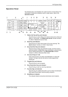
FAX System, Operation Panel, Telephone jack, LINE jack, Main power switch
 |
View all Kyocera KM-1820 manuals
Add to My Manuals
Save this manual to your list of manuals |
Page 16 highlights
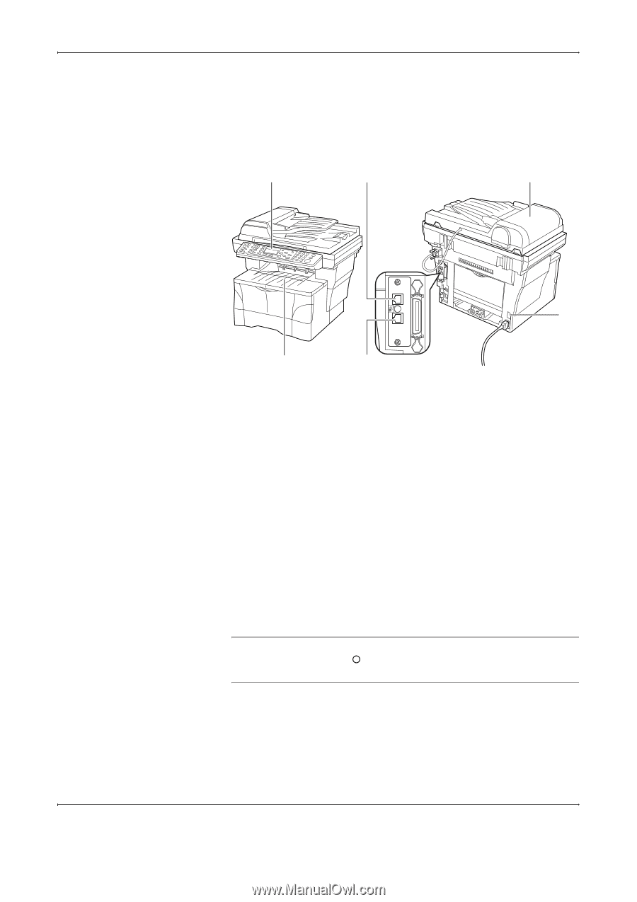
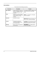
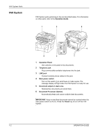
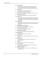
FAX System Parts FAX System FAX System parts pertaining to fax are described below. For information on other parts, refer to the Operation Guide. 1 3 6 4 5 2 1 Operation Panel Use controls on this panel to fax documents. 2 Telephone jack Plug commercially-available telephones into this jack. 3 LINE jack Connect modular phone cables to this jack. 4 Main power switch Turn on this switch (|) to send faxes or make copies. The message display will light when the FAX System is ready for use. 5 Document output or stack area Received fax documents are stored here. 6 Document Processor (Option) Automatically feeds and scans multiple sheet documents. IMPORTANT: Keep in mind that documents cannot be received when the main power switch is off ({). Press the Power key to turn off the FAX System. 1-2 OPERATION GUIDE
-
 1
1 -
2
-
3
-
4
-
5
-
6
-
7
-
8
-
9
-
10
-
 11
11 -
 12
12 -
 13
13 -
 14
14 -
 15
15 -
 16
16 -
 17
17 -
 18
18 -
 19
19 -
 20
20 -
 21
21 -
22
-
23
-
24
-
25
-
26
-
27
-
28
-
29
-
30
-
31
-
32
-
33
-
34
-
35
-
36
-
37
-
38
-
39
-
40
-
41
-
42
-
43
-
44
-
45
-
46
-
47
-
48
-
49
-
50
-
51
-
52
-
53
-
54
-
55
-
56
-
57
-
58
-
59
-
60
-
61
-
62
-
63
-
64
-
65
-
66
-
67
-
68
-
69
-
70
-
71
-
72
-
73
-
74
-
75
-
76
-
77
-
78
-
79
-
80
-
81
-
82
-
83
-
84
-
85
-
86
-
87
-
88
-
89
-
90
-
91
-
92
-
93
-
94
-
95
-
96
-
97
-
98
-
99
-
100
-
101
-
102
-
103
-
104
-
105
-
106
-
107
-
108
-
109
-
110
-
111
-
112
-
113
-
114
-
115
-
116
-
117
-
118
-
119
-
120
-
121
-
122
-
123
-
124
-
125
-
126
-
127
-
128
-
129
-
130
-
131
-
132
-
133
-
134
-
135
-
136
-
137
-
138
-
139
-
140
-
141
-
142
-
143
-
144
-
145
-
146
-
147
-
148
-
149
-
150
-
151
-
152
-
153
-
154
-
155
-
156
-
157
-
158
-
159
-
160
-
161
-
162
-
163
-
164
-
165
-
166
-
167
-
168
-
169
-
170
-
171
-
172
-
173
-
174
-
175
-
176
-
177
-
178
-
179
-
180
-
181
-
182
-
183
-
184
-
185
-
186
-
187
-
188
-
189
-
190
-
191
-
192
-
193
-
194
-
195
-
196
-
197
-
198
-
199
-
200
 |
 |