Kyocera KM-8030 PRESCRIBE Commands Technical Reference Manual - Rev. 4.7 - Page 112
Permanent Parameters, M5/M6/M7/M8-Host buffer size
 |
View all Kyocera KM-8030 manuals
Add to My Manuals
Save this manual to your list of manuals |
Page 112 highlights
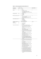
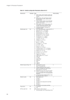
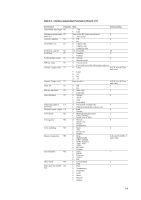
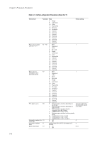
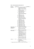
Chapter 6 Permanent Parameters b I0-Name of the partition in memory card The FRPO I0 specifies a memory card partition name to be automatically read at power up. Only one partition may be specified. The data read from the named partition at power up will be available to users accessing the currently-active interface. The command uses the following format: FRPO I0, 'partition-name'; Note that a comma must be placed after the I0 parameter. The partition name should not exceed 15 printable ASCII characters (20H through 7EH) and be enclosed by single or double quotation marks. Partition names are case-sensitive so the correct upper and lowercase characters must be used in the FRPO I0 string. The FRPO M2 parameter enables the printing system to read the partition name into a port apart from the currently active one. For instance, if the active port were the parallel port but the M2 parameter specified the serial port, then the memory card data would be available to users accessing the serial interface. c M1-Status send control The FRPO M1 parameter enables the user to receive printing system status information. By sending CTRL-T (Hex 14) from the host computer to the printing system. d M3-Host buffer mode The M3 parameter determines the automatic or fixed host buffer mode. If the M3 value is 0 (automatic), the first data arriving from the computer go into buffer #1, regardless of which interface they arrive on. While buffer #1 is in use, if data also begin to arrive on a second interface they are stored in buffer #2. The printing system will print these data after it has finished printing the job received through buffer #1. The general rule is that data go to the available buffer. If the M3 value is 1 (fixed), buffer #1 is fixed to receive only the data arriving in the parallel interface; and buffer #2 is fixed in the option interface (if installed). The first data arriving on one of the interfaces go into its fixed, dedicated buffer and the printing system begins printing these data and continues as above. The factory setting of the total host buffer size is 60 kilobytes or 500 kilobytes depending on the model. This can be altered by the FRPO H8 command. If you alter the buffer size, you must reset the printing system to bring the change in effect. e M5/M6/M7/M8-Host buffer size The printing system utilizes each one buffer for its interfaces. This enables simultaneous receiving of data from the different host computers. The FRPO M5, M6, M7, and M8 parameters determine the ratio among the sizes allocated to these buffers. Parameters M6 and M7 are provided for option interfaces. For example, to allocate the buffers with size ratio of 5:1, use the following format: !R! FRPO M3, 1; FRPO M5, 5; FRPO M6, 1; EXIT; f Ignored in some emulation modes. g Models of low-end category only. h A3/ledger models only. 6-12
-
 1
1 -
2
-
3
-
4
-
5
-
6
-
7
-
8
-
9
-
10
-
11
-
12
-
13
-
14
-
15
-
16
-
17
-
18
-
19
-
20
-
21
-
22
-
23
-
24
-
25
-
26
-
27
-
28
-
29
-
30
-
31
-
32
-
33
-
34
-
35
-
36
-
37
-
38
-
39
-
40
-
41
-
42
-
43
-
44
-
45
-
46
-
47
-
48
-
49
-
50
-
51
-
52
-
53
-
54
-
55
-
56
-
57
-
58
-
59
-
60
-
61
-
62
-
63
-
64
-
65
-
66
-
67
-
68
-
69
-
70
-
71
-
72
-
73
-
74
-
75
-
76
-
77
-
78
-
79
-
80
-
81
-
82
-
83
-
84
-
85
-
86
-
87
-
88
-
89
-
90
-
91
-
92
-
93
-
94
-
95
-
96
-
97
-
98
-
99
-
100
-
101
-
102
-
103
-
104
-
105
-
106
-
 107
107 -
 108
108 -
 109
109 -
 110
110 -
 111
111 -
 112
112 -
 113
113 -
 114
114 -
 115
115 -
 116
116 -
 117
117 -
118
-
119
-
120
-
121
-
122
-
123
-
124
-
125
-
126
-
127
-
128
-
129
-
130
-
131
-
132
-
133
-
134
-
135
-
136
-
137
-
138
-
139
-
140
-
141
-
142
-
143
-
144
-
145
-
146
-
147
-
148
-
149
-
150
-
151
-
152
-
153
-
154
-
155
-
156
-
157
-
158
-
159
-
160
-
161
-
162
-
163
-
164
-
165
-
166
-
167
-
168
-
169
-
170
-
171
-
172
-
173
-
174
-
175
-
176
-
177
-
178
-
179
-
180
-
181
-
182
-
183
-
184
-
185
-
186
-
187
-
188
-
189
-
190
-
191
-
192
-
193
-
194
-
195
-
196
-
197
-
198
-
199
-
200
-
201
-
202
-
203
-
204
-
205
-
206
-
207
-
208
-
209
-
210
-
211
-
212
-
213
-
214
-
215
-
216
-
217
-
218
-
219
-
220
-
221
-
222
-
223
-
224
-
225
-
226
-
227
-
228
-
229
-
230
-
231
-
232
-
233
-
234
-
235
-
236
-
237
-
238
-
239
-
240
-
241
-
242
-
243
-
244
-
245
-
246
-
247
-
248
-
249
-
250
-
251
-
252
-
253
-
254
-
255
-
256
-
257
-
258
-
259
-
260
 |
 |