Kyocera KM-8030 PRESCRIBE Commands Technical Reference Manual - Rev. 4.7 - Page 213
Setting the Scaling Points, Sample KC-GL Program, HP 7550A Emulation [KC-GL] Mode 8, Coordinate Values
 |
View all Kyocera KM-8030 manuals
Add to My Manuals
Save this manual to your list of manuals |
Page 213 highlights
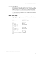
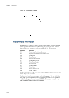
HP 7550A Emulation [KC-GL] (Mode 8) Setting the Scaling Points At power-up, scaling point P1 will be in the lower left corner of the paper, the default plot position. Point P2 is always diagonally opposite to P1. These two points define the diagonal of a rectangle, which by default is centered on the paper. P1 and P2 can be moved by an instruction which defines any rectangle, independent of the actual paper size. The default positions of the scaling points in modes A and B are listed at the end of this section as Coordinate Values. Sample KC-GL Program The following file draws circles according to the KC-GL instructions. The result appears in Figure 7. 30. on page 102. IN; IP0,0,400,400; SC0,1,0,1; "Initialize plotter" "P1 and P2: 1-cm square1" "Scale: user unit = 1 cm" DT ; SP1; "Select pen 1" PA10,19; "Move pen" CI.1;PR0,-.1; "Draw four circles" CI.2;PR0,-.2; CI.4;PR0,-.4; CI.8;PR0,-.8; SP2; "Select pen 2" CI1.6;PR0,-1.6; "Draw two circles" CI3.2;PR0,-3.2; SP8; "Select pen 8" CI.1;PR.5,-.5; "Draw circle" SP2; "Select pen 2" CS0;SI.2,.3;LBCURSOR* ; "Print label2" SP; 1 This instruction locates P1 at 0, 0 and P2 at 400, 400 in plotter units. 400 plotter units=1 cm (0.025 mm x 400). 2 ETX (End of Text, character code 03) is required as a terminator. 7-101
-
 1
1 -
2
-
3
-
4
-
5
-
6
-
7
-
8
-
9
-
10
-
11
-
12
-
13
-
14
-
15
-
16
-
17
-
18
-
19
-
20
-
21
-
22
-
23
-
24
-
25
-
26
-
27
-
28
-
29
-
30
-
31
-
32
-
33
-
34
-
35
-
36
-
37
-
38
-
39
-
40
-
41
-
42
-
43
-
44
-
45
-
46
-
47
-
48
-
49
-
50
-
51
-
52
-
53
-
54
-
55
-
56
-
57
-
58
-
59
-
60
-
61
-
62
-
63
-
64
-
65
-
66
-
67
-
68
-
69
-
70
-
71
-
72
-
73
-
74
-
75
-
76
-
77
-
78
-
79
-
80
-
81
-
82
-
83
-
84
-
85
-
86
-
87
-
88
-
89
-
90
-
91
-
92
-
93
-
94
-
95
-
96
-
97
-
98
-
99
-
100
-
101
-
102
-
103
-
104
-
105
-
106
-
107
-
108
-
109
-
110
-
111
-
112
-
113
-
114
-
115
-
116
-
117
-
118
-
119
-
120
-
121
-
122
-
123
-
124
-
125
-
126
-
127
-
128
-
129
-
130
-
131
-
132
-
133
-
134
-
135
-
136
-
137
-
138
-
139
-
140
-
141
-
142
-
143
-
144
-
145
-
146
-
147
-
148
-
149
-
150
-
151
-
152
-
153
-
154
-
155
-
156
-
157
-
158
-
159
-
160
-
161
-
162
-
163
-
164
-
165
-
166
-
167
-
168
-
169
-
170
-
171
-
172
-
173
-
174
-
175
-
176
-
177
-
178
-
179
-
180
-
181
-
182
-
183
-
184
-
185
-
186
-
187
-
188
-
189
-
190
-
191
-
192
-
193
-
194
-
195
-
196
-
197
-
198
-
199
-
200
-
201
-
202
-
203
-
204
-
205
-
206
-
207
-
 208
208 -
 209
209 -
 210
210 -
 211
211 -
 212
212 -
 213
213 -
 214
214 -
 215
215 -
 216
216 -
 217
217 -
 218
218 -
219
-
220
-
221
-
222
-
223
-
224
-
225
-
226
-
227
-
228
-
229
-
230
-
231
-
232
-
233
-
234
-
235
-
236
-
237
-
238
-
239
-
240
-
241
-
242
-
243
-
244
-
245
-
246
-
247
-
248
-
249
-
250
-
251
-
252
-
253
-
254
-
255
-
256
-
257
-
258
-
259
-
260
 |
 |