Kyocera TASKalfa 181 Fax System (R) Installation Instructions
Kyocera TASKalfa 181 Manual
 |
View all Kyocera TASKalfa 181 manuals
Add to My Manuals
Save this manual to your list of manuals |
Kyocera TASKalfa 181 manual content summary:
- Kyocera TASKalfa 181 | Fax System (R) Installation Instructions - Page 1
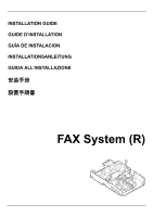
INSTALLATION GUIDE GUIDE D'INSTALLATION GUÍA DE INSTALACION INSTALLATIONSANLEITUNG GUIDA ALL'INSTALLAZIONE FAX System (R) - Kyocera TASKalfa 181 | Fax System (R) Installation Instructions - Page 2
- Kyocera TASKalfa 181 | Fax System (R) Installation Instructions - Page 3
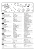
M3 x 8 9 D Molla della piastra 1 E Cavo 1 D Plate spring 1 E Wire 1 F Upper plate 1 G Lower plate 1 H Operation section sheet 120 V specification 4 230 V specification 8 I One-touch securing sheet 1 J Fax plate 1 E Câble 1 F Plateau supérieur 1 G Plateau inférieur 1 H Feuille de la - Kyocera TASKalfa 181 | Fax System (R) Installation Instructions - Page 4
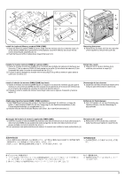
tape and/or cushioning material from supplied parts. Procedure Turn the MFP's power switch to OFF and unplug the MFP from the power supply before installing the fax system. Option Q Module de mémoire DIMM (32Mo 1 Veillez à retirer les morceaux de bande adhésive et/ou les matériaux de rembourrage - Kyocera TASKalfa 181 | Fax System (R) Installation Instructions - Page 5
end of the module down toward the board. [2] 5 Removing the covers 3. Remove the 5 screws (4) from the rear side of the machine to remove the cover (5). Installer le module mémoire DIMM (en option) (32Mo) 1. Insérer le module de mémoire DIMM (Q) en l'inclinant dans la fente de mémoire (2) de façon - Kyocera TASKalfa 181 | Fax System (R) Installation Instructions - Page 6
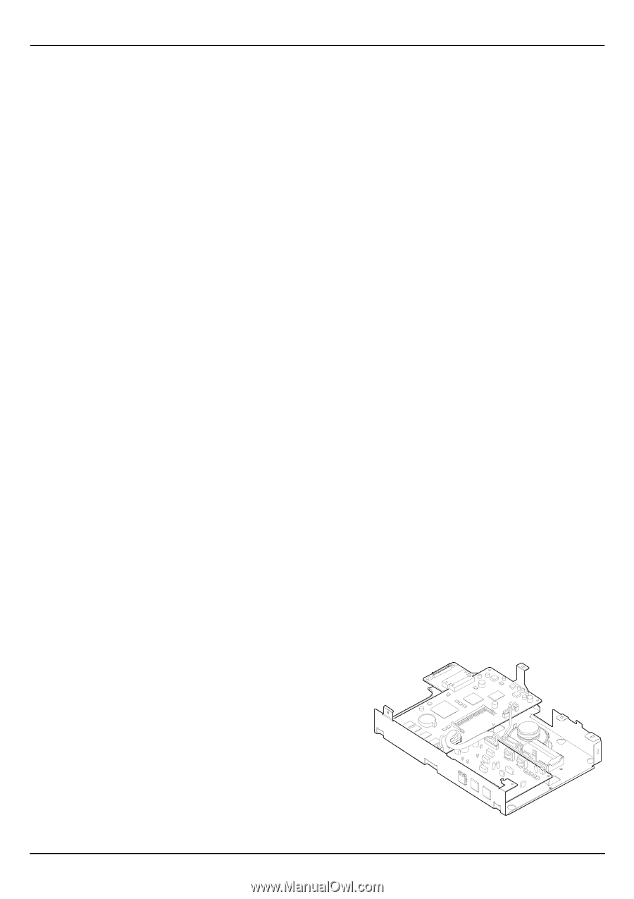
4. Remove the screw (6) to remove the mounting plates ((7) and (8)). Installing the plate spring 5. Use the M3 x 8 screw (C) to attach the C ) para fijar el resorte de la placa (D) en la cubierta de blindaje. Instale el conjunto de la tarjeta de circuitos de control de facsímil. 6. Enchufar el - Kyocera TASKalfa 181 | Fax System (R) Installation Instructions - Page 7
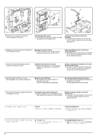
10 12 12 E E 11 11 A 7. Plug the white connector on the wire (E) into YC10 (10) on the engine circuit board. 8. Fit the 2 hooks (11) on the fax control circuit board assembly (A) into the latch (12) in the shielding cover. 7. Raccordez le connecteur blanc du câble (E) à YC10 (10) de la - Kyocera TASKalfa 181 | Fax System (R) Installation Instructions - Page 8
C C C 13 C* C C* 13 A C* 9. Secure the fax control circuit board assembly (A) using the five M3 x 8 screws (C). When fastening the lower-right screw (C*), take care not to pinch the wire (13) 14 10. Remove the screw (14) from the machine. 9. Fixez l'ensemble de carte à circuits de - Kyocera TASKalfa 181 | Fax System (R) Installation Instructions - Page 9
connect it to the telephone line. For 100 V, 120 V or 220 V specification or for Australia, use the supplied modular cord (B). In New Zealand, attach V o para Australia, utilice el cable modular (B). Para Nueva Zelandia, instale la cubierta del conector modular (P) en el terminal TEL T1 (17). 11 - Kyocera TASKalfa 181 | Fax System (R) Installation Instructions - Page 10
20 19 21 18 18 Installing the operation section sheet 15. Insert a flat-head screwdriver into the latch and remove the cover (18). 16. Remove the left cover of the operation - Kyocera TASKalfa 181 | Fax System (R) Installation Instructions - Page 11
H 22 21 23 23 18. Remove the operation section sheet (22) and replace it with the operation section sheet (H) for fax of the corresponding language. 19.Refit the operation section sheet cover (21) removed in step 17 by inserting the 2 pawls (23) on the right side of the cover into their - Kyocera TASKalfa 181 | Fax System (R) Installation Instructions - Page 12
unique (I) ne bloque aucune touche à touche unique. 20. Volver a instalar la cubierta (18), desmontada en el paso 15, insertando el trinquete (24) en su ranura. Instale la hoja de seguridad de un toque. 21. Desmonte el papel de liberación de la hoja de seguridad de un toque (I). 22. Pegue la hoja - Kyocera TASKalfa 181 | Fax System (R) Installation Instructions - Page 13
shown in the illustration. Attach the fax plate.(120 and 230 V specifications only) 25. Incurvate the fax plate (J) a little and then insert en las posiciones de la placa de facsímil (J) que aparecen en la figura. Instale la placa de facsímil.(especificaciones de 120 y 230 V, solamente) 25. Curve - Kyocera TASKalfa 181 | Fax System (R) Installation Instructions - Page 14
touch sheet.(120 and 230 V specifications only) 27. Separate the one-touch sheet (K) for the supported language into 2 parts and (H) qui correspond aux langues non utilisées, et la feuille à touche unique (K). Instale la hoja de un toque. (especificaciones de 120 y 230 V, solamente) 27. Separar - Kyocera TASKalfa 181 | Fax System (R) Installation Instructions - Page 15
, refer to page 14 to attach the label. Execute the maintenance mode. After installation is complete, the fax control circuit board must be initialized by executing the maintenance mode U601/U602. For details, see the service manual. Fixer l'étiquette de conformité (100V et 120 V uniquement). 29 - Kyocera TASKalfa 181 | Fax System (R) Installation Instructions - Page 16
Australia and New Zealand Attach the approval label R Only Australia specification Attach the A-TICK label (R) onto the shield cover (5) after wiping the cover with alcohol . A-TICK label Only New Zealand specification Attach the TELEPERMIT label (R) 5 onto the shield cover (5) after wiping - Kyocera TASKalfa 181 | Fax System (R) Installation Instructions - Page 17
MEMO - Kyocera TASKalfa 181 | Fax System (R) Installation Instructions - Page 18
MEMO - Kyocera TASKalfa 181 | Fax System (R) Installation Instructions - Page 19
MEMO - Kyocera TASKalfa 181 | Fax System (R) Installation Instructions - Page 20
2009. 3 303MZ56711
-
 1
1 -
 2
2 -
 3
3 -
 4
4 -
 5
5 -
 6
6 -
 7
7 -
8
-
9
-
10
-
11
-
12
-
13
-
14
-
15
-
16
-
17
-
18
-
19
-
20
 |
 |
FAX System (R)
INSTALLATION GUIDE
GUIDE D’INSTALLATION
GUÍA DE INSTALACION
INSTALLATIONSANLEITUNG
GUIDA ALL’INSTALLAZIONE
安装手册
設置手順書