LG 42LC7D Owner's Manual (English) - Page 25
VCR SETUP, When connecting with an antenna - owners manual
 |
UPC - 719192171145
View all LG 42LC7D manuals
Add to My Manuals
Save this manual to your list of manuals |
Page 25 highlights
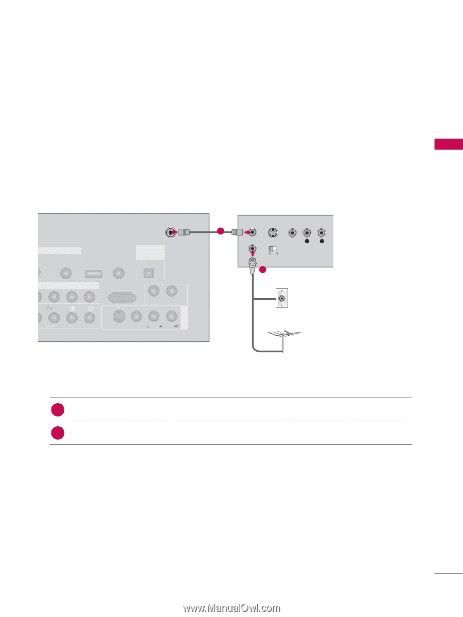
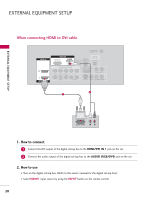
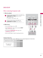
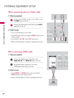
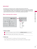
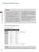
EXTERNAL EQUIPMENT SETUP VCR SETUP I To avoid picture noise (interference), leave an adequate distance between the VCR and TV. I Use the ISM feature in the Option menu to avoid having a fixed image remain on the screen for a long peri- od of time (Only Plasma TV model). If the 4:3 picture format is used; the fixed images on the sides of the screen may remain visible on the screen. This phenomenon is common to all manufactures and in consequence the manufactures warr(ant) y does not cover the product bearing this phenomenon. When connecting with an antenna ANTENNA/ CABLE IN GB IN DIGITAL AUDIO REMOTE AUDIO OUT (RGB/DVI) SERVICE CONTROL IN OPTICAL MPONENT IN RS-232C IN (CONTROL & SERVICE) AUDIO OUT EO AUDIO S-VIDEO VIDEO (MONO) AUDIO AV IN 1 1 ANT OUT S-VIDEO VIDEO L R ANT IN OUTPUT SWITCH 2 Wall Jack Antenna 1. How to connect 1 Connect the RF antenna out socket of the VCR to the ANTENNA/CABLE IN socket on the set. 2 Connect the antenna cable to the RF antenna in socket of the VCR. 2. How to use I Set VCR output switch to 3 or 4 and then tune TV to the same channel number. I Insert a video tape into the VCR and press PLAY on the VCR. (Refer to the VCR owner's manual.) 23 ( )
-
 1
1 -
2
-
3
-
4
-
5
-
6
-
7
-
8
-
9
-
10
-
11
-
12
-
13
-
14
-
15
-
16
-
17
-
18
-
19
-
 20
20 -
 21
21 -
 22
22 -
 23
23 -
 24
24 -
 25
25 -
 26
26 -
 27
27 -
 28
28 -
 29
29 -
 30
30 -
31
-
32
-
33
-
34
-
35
-
36
-
37
-
38
-
39
-
40
-
41
-
42
-
43
-
44
-
45
-
46
-
47
-
48
-
49
-
50
-
51
-
52
-
53
-
54
-
55
-
56
-
57
-
58
-
59
-
60
-
61
-
62
-
63
-
64
-
65
-
66
-
67
-
68
-
69
-
70
-
71
-
72
-
73
-
74
-
75
-
76
-
77
-
78
-
79
-
80
-
81
-
82
-
83
-
84
-
85
-
86
-
87
-
88
-
89
-
90
-
91
-
92
-
93
-
94
-
95
-
96
-
97
-
98
-
99
-
100
-
101
-
102
-
103
-
104
-
105
-
106
-
107
-
108
-
109
-
110
-
111
-
112
 |
 |