LG 42LG50 Owner's Manual (English) - Page 35
VCR SETUP, Antenna Connection - warranty
 |
UPC - 719192173019
View all LG 42LG50 manuals
Add to My Manuals
Save this manual to your list of manuals |
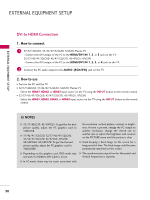
Page 35 highlights
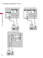
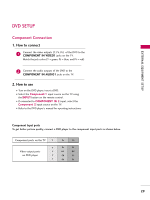
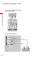
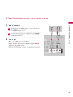
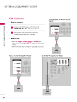
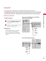
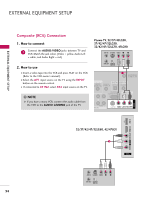
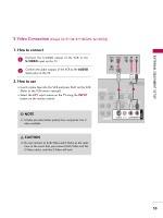
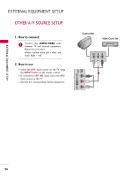
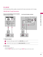
EXTERNAL EQUIPMENT SETUP VCR SETUP I To avoid picture noise (interference), leave an adequate distance between the VCR and TV. I Use the ISM feature in the Option menu to avoid having a fixed image remain on the screen for a long period of time (Plasma TV models only). If the 4:3 picture format is used; the fixed images on the sides of the screen may remain visible on the screen. This phenomenon is common to all TVs and is not covered by warranty. Antenna Connection 1. How to connect Plasma TV, 32/37/42LG30, 37/42/47/52LG50, 32/42/47/52LG70, 47LG90 1 Connect the RF antenna out socket of the VCR to the ANTENNA/CABLE IN sock- ANTENNA/ CABLE IN et on the TV. UDIO OUT COAXIAL 1 2 Connect the antenna cable to the RF antenna in socket of the VCR. AUDIO OUT E) 2. How to use I Set VCR output switch to 3 or 4 and then tune TV to the same channel number. I Insert a video tape into the VCR and press PLAY on the VCR. (Refer to the VCR owner's manual.) EO L(MONO) AUDIO R ANT OUT S-VIDEO VIDEO L R ANT IN OUTPUT SWITCH Wall Jack 2 Antenna AV IN 1 COMP AUDIO 32/37/42/47/52LG60, 42/47LGX COAX OPTIC 1 S-VIDEO VIDEO L R ANT OUT RS-232C IN ANTENNA/ CABLE IN (SERVICE ONLY) OUTPUT SWITCH ANT IN Wall Jack 2 REMOTE CONTROL IN Antenna 33
-
 1
1 -
2
-
3
-
4
-
5
-
6
-
7
-
8
-
9
-
10
-
11
-
12
-
13
-
14
-
15
-
16
-
17
-
18
-
19
-
20
-
21
-
22
-
23
-
24
-
25
-
26
-
27
-
28
-
29
-
 30
30 -
 31
31 -
 32
32 -
 33
33 -
 34
34 -
 35
35 -
 36
36 -
 37
37 -
 38
38 -
 39
39 -
 40
40 -
41
-
42
-
43
-
44
-
45
-
46
-
47
-
48
-
49
-
50
-
51
-
52
-
53
-
54
-
55
-
56
-
57
-
58
-
59
-
60
-
61
-
62
-
63
-
64
-
65
-
66
-
67
-
68
-
69
-
70
-
71
-
72
-
73
-
74
-
75
-
76
-
77
-
78
-
79
-
80
-
81
-
82
-
83
-
84
-
85
-
86
-
87
-
88
-
89
-
90
-
91
-
92
-
93
-
94
-
95
-
96
-
97
-
98
-
99
-
100
-
101
-
102
-
103
-
104
-
105
-
106
-
107
-
108
-
109
-
110
-
111
-
112
-
113
-
114
-
115
-
116
-
117
-
118
-
119
-
120
-
121
-
122
-
123
-
124
-
125
-
126
-
127
-
128
-
129
-
130
-
131
-
132
-
133
-
134
-
135
-
136
-
137
-
138
-
139
-
140
-
141
-
142
-
143
-
144
-
145
-
146
-
147
-
148
-
149
-
150
-
151
-
152
 |
 |