LG 42PM1M Service Manual
LG 42PM1M - LG - 42" Plasma Panel Manual
 |
UPC - 719192169562
View all LG 42PM1M manuals
Add to My Manuals
Save this manual to your list of manuals |
LG 42PM1M manual content summary:
- LG 42PM1M | Service Manual - Page 1
website:http://biz.LGservice.com e-mail:http://www.LGEservice.com/techsup.html PLASMA MONITOR SERVICE MANUAL CHASSIS : RF-052A MODEL : 42PM1M 42PM1M-TA CAUTION BEFORE SERVICING THE CHASSIS, READ THE SAFETY PRECAUTIONS IN THIS MANUAL. - LG 42PM1M | Service Manual - Page 2
CONTENTS SAFETY PRECAUTIONS 3 DESCRIPTION OF CONTROLS 4 SPECIFICATIONS 8 ADJUSTMENT INSTRUCTIONS 10 TROUBLE SHOOTING GUIDE 15 PRINTED CIRCUIT BOARD 24 BLOCK DIAGRAM 26 EXPLODED VIEW 28 EXPLODED VIEW PARTS LIST 29 REPLACEMENT PARTS LIST 30 SCHEMATIC DIAGRAM -2- - LG 42PM1M | Service Manual - Page 3
the same components as recommended in this manual to prevent X-RADIATION, Shock, Fire, introduced during the service operation. If any fuse (or Fusible Resistor) in this monitor is blown, of shock hazard and the set must be checked and repaired before it is returned to the customer. Leakage Current - LG 42PM1M | Service Manual - Page 4
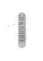
OF CONTROLS MUTE switches the sound on or off. MULTIMEDIA selects the Component, RGB or DVI modes. INPUT LIST (option) displays the programme table. D /E Selects a menu option. F / G (Volume Up/Down) Increases/decreases sound level. Adjusts menu settings. OK accepts your selection or displays the - LG 42PM1M | Service Manual - Page 5
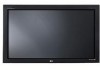
ON/OFF INPUT SELECT MENU VOL 1 23 4 5 6 1. Main Power Button 2. Remote Control Sensor 3. Power Standby Indicator Illuminates red in standby mode, Illuminates green when the set is turned on 4. INPUT SELECT Button 5. MENU Displays on screen menus one by one. Exits the current menu. Memorizes - LG 42PM1M | Service Manual - Page 6
REMOTE CONTROL RS-232C INPUT HDMI/ (CONTROL/SERVICE) DVI(VIDEO) AUDIO INPUT RGB OUTPUT AUDIO R L R L RGB INPUT VARIABLE AUDIO OUT EXTERNAL SPEAKER Y PB PR VIDEO R L AUDIO COMPONENT INPUT 2 MONITOR OUPUT COMPONENT INPUT 1 A/V INPUT R L (MONO) AUDIO VIDEO S-VIDEO R - LG 42PM1M | Service Manual - Page 7
LG TV AS mark Owner's Manual Power Cord MUTE POWER INPUT MULTIMEDIA I/II LIST/ ARC MENU OK VOL VOL 123 456 789 PSM 0 SSM SPLIT ZOOM TEXT/ SLEEP REVEAL ? SIZE MODE MIX UPDATE Q.VIEW TIME HOLD INDEX i Remote Control handset 1.5V 1.5V Alkaline batteries Optional Extras - Optional - LG 42PM1M | Service Manual - Page 8
change without notice for improvement. V Application Range This spec is applied to the 42"PDP TV used RF-052A Chassis. V Specification Each part is Model Name 42PM1M-TA Market Remark Non-EU Safety : IEC/EN60065, EMI : CISPR13 V General Specification 1. Module Specification No Item 1 Display - LG 42PM1M | Service Manual - Page 9
audio out(1EA) Variable Audio out(1EA) Discrete IR Remark Except 42PM1MB, 50PM1MB, 42PM3MVB Except 42PM1MB, 50PM1MB, 42PM3MVB Except 42PM1MB, 50PM1MB, 42PM3MVB 42PM1M, 42PM1MA, 50PM1M, 50PM1MA 42PM3MV, 42PM3MVA 42PM1MB, 50PM1MB, 42PM3MVB 42PM1M, 42PM1MA, 50PM1M, 50PM1MA, 42PM3MV, 42PM3MVA -9- - LG 42PM1M | Service Manual - Page 10
instructions is applied all of the 42" PDP TV POWER ON KEY on R/C for adjustment. 2) OSD display and screen display 100% full White pattern. [ Set is activated Stand-by state (LED_R). And you have to Download in Stand_by power state. (Fig. 2-1) 3) Select proper CH_memory file(*.nvm) for each model - LG 42PM1M | Service Manual - Page 11
the data P807 P801 P802 P803 (Fig. 3) Connection diagram of power adjustment for measuring 5. EDID (The Extended Display Identification Data)/ DDC (Display Data Channel) download 5-1. Required Test Equipment 1) Adjusting PC with S/W for writing EDID Data.(S/W : EDID TESTER Ver.2.5) 2) A Jig - LG 42PM1M | Service Manual - Page 12
the CA-100, then stick sensor to PDP module surface when you adjust. O For manual adjustment, it is also possible by the following sequence. 1) Select white pattern of heat-run mode by pressing power on key on remote control for adjustment then operate heat run more than 15 minutes. 2) As below Fig - LG 42PM1M | Service Manual - Page 13
-925) V If Minimum Black Level and/or Maximum White Level is not correct, Do select 100% Color Bar Pattern. 9-1. Required Test Equipment 1) Remote controller for adjustment 2) 802F Pattern Generator (Which has VGA 60Hz PC Format output with standard (0.7Vpp) Vertical 16 Gray Scale pattern as Fig.10 - LG 42PM1M | Service Manual - Page 14
10. Default value in adjustment mode 10-1. Auto Color Balance (Component/RGB) Auto Color Balance(HEX) Auto-RGB Source Red Offset1 Green Offset1 Blue Offset1 Red Offset2 Green Offset2 Blue Offset2 Red Gain Green Gain Blue Gain Reset G To Set Cortez 22 24 23 45 43 37 014 031 011 G To Set (Fig. 11) - LG 42PM1M | Service Manual - Page 15
TROUBLE SHOOTING GUIDE 1. Power Board 1-1. The whole flowchart which it follows in voltage output state output come out? Doesn't the No St-by 5V signal come out? Doesn't the No 5V Monitor signal come out? Doesn't the VSC signal RL-ON come out? Yes Yes No 3. Check the St-by 5V - LG 42PM1M | Service Manual - Page 16
1-2. Sony Power Board Structure 1 2 3 T502: Vs Trans T702: Va Trans T101: St-by Trans T103: Low Voltage Trans - 16 - - LG 42PM1M | Service Manual - Page 17
1-3. Sanken, LGIT Power Board Structure 1 2 3 T221: Vs Trans T271: Va Trans T121: St-by Trans T201: Low Voltage Trans - 17 - - LG 42PM1M | Service Manual - Page 18
Board Cable connected? Yes After the cable connect is remved to Power Board(except the CN101 connection cable), the AC voltage marking is authorized on manual. When ST-BY 5V is not operated, replace Power Board. Plug in power cord. Connect the Cable. Replace the Fuse. Connect the Cable. - 18 - LG 42PM1M | Service Manual - Page 19
No normal? Yes Is the No VSC Board normal? Yes Is the COF of X, Y, Z No normal ? Is output the normality Low/High voltage except Stand-by 5V? No Replace Power Board. After connecting well each connector, No the normality it operates? Replace the connector. Is the output voltage Is the - LG 42PM1M | Service Manual - Page 20
Board normal? Yes Is the No VSC Board normal? Yes Is the COF of X, Y, Z No normal? Is output the normality Low/High voltage except Stand-by 5V? No Replace the Power Board. After connecting well each connector, No the normality it operates? Replace the connector. Is the output voltage Is - LG 42PM1M | Service Manual - Page 21
5. In case of occurring strange screen into specific mode 5-1. In case the OSD does not displayed (1) Symptom ¯ LED is green ¯ The minute discharged continuously becomes accomplished from module (2) Check following Is the LVDS cable No normal ? Is the LVDS cable Yes - LG 42PM1M | Service Manual - Page 22
input mode (RF, AV, Component, RGB, DVI). (2) Check following ¯ Check the all input mode should become normality display. ¯ Check the Video(Main)/Data(Sub), Video(Main)/Video(Sub) should become normality display from the PIP mode or DW mode. (Re-Check it Swap) (3) In case of becomes unusual - LG 42PM1M | Service Manual - Page 23
6. In case of no sound (1) Symptom ¯ LED is green ¯ Screen display but sound is not output (2) Check following Is the SPK cable No normal? Yes Is the SPK cable connected well? Yes Replace SPK cable No - LG 42PM1M | Service Manual - Page 24
MAIN(TOP) PRINTED CIRCUIT BOARD MAIN(BOTTOM) - 24 - - LG 42PM1M | Service Manual - Page 25
RCA(TOP) RCA(BOTTOM) CONTROL POWER SWITCH - 25 - - LG 42PM1M | Service Manual - Page 26
RCA Block Diagram Cable BLOCK DIAGRAM - 26 - - LG 42PM1M | Service Manual - Page 27
Scart Block Diagram Cable - 27 - - LG 42PM1M | Service Manual - Page 28
EXPLODED VIEW 300 305 301 310 530 304 103 101 540 541 501 520 303 302 206 202 200 104 102 207 201 205 203 204 560 580 400 410 561 - 28 - - LG 42PM1M | Service Manual - Page 29
HAND INSERT 42X2 X-LEFT(TCP) PWB(PCB) ASSEMBLY,DISPLAY XRRT ASSY HAND INSERT 42X2 X-RIGHT (TCP) PWB(PCB) ASSEMBLY,DISPLAY YSUS ASSY HAND INSERT FOR 42X2 PWB(PCB) ASSEMBLY,DISPLAY ZSUS ASSY HAND INSERT FOR 42X2 CABINET ASSEMBLY, 42PM12X RF043E 2TONE SUPPORTER, ASSY AL SUPP. FILTER TOP APPLY 42PM10 AL - LG 42PM1M | Service Manual - Page 30
,9V LDO LM75CIMX-3 8P/SOP R/TP PQ12RD21 4SIP ST REGULATOR FLI8532BD-LF GENESIS 416P/PBGA 24LC256-I/SM 8P,SOP TP 256K 2.00V 9CB2 PDP RF052A 42PM1M K4D261638F-LC50,LF TSOPII 66P K4D261638F-LC50,LF TSOPII 66P TRANSISTOR IC1202 IC1203 IC503 IC504 Q100 Q1000 Q1001 Q1002 Q1003 Q1004 Q101 Q101 Q102 Q102 - LG 42PM1M | Service Manual - Page 31
LOCA. NO C1019 C103 C1030 C1043 C1046 C1047 C1050 C1051 C1064 C1065 C1066 C1067 C1068 C1069 C1071 C1073 C108 C1082 C1083 C1084 C1085 C1087 C1098 C1099 C1102 C1105 C1107 C1108 C1110 C1116 C1117 C1118 C1120 C1126 C113 C1136 C1138 C114 C1148 C1149 C1150 C1151 C1156 C1159 C1160 C1162 C1165 C1166 C1185 - LG 42PM1M | Service Manual - Page 32
For Capacitor & Resistors, the charactors at 2nd and 3rd digit in the P/No. means as follows; CC, CX, CK, CN : Ceramic CQ : Polyestor CE : Electrolytic RD : Carbon Film RS : Metal Oxide Film RN : Metal Film RF : Fusible LOCA. NO C403 C407 C413 C418 C419 C421 C425 C444 C451 C456 C457 C462 C463 - LG 42PM1M | Service Manual - Page 33
140-313B 6600VM2006A 6600VR1004A TACT 2LEAD 160G(TA) LG C&D 5V 0.001A TACT 2LEAD 160G(TA) LG C&D 5V 0.001A TACT 2LEAD 160G(TA) LG C&D 5V 0.001A TACT 2LEAD 160G(TA) LG C&D 5V 0.001A TACT 2LEAD 160G(TA) LG C&D 5V 0.001A TACT 2LEAD 160G(TA) LG C&D 5V 0.001A SDDF3PATP011 POSTEC UNIVERSAL 250V 4A SKHMPW - LG 42PM1M | Service Manual - Page 34
DC1R019NDA JAE 1.0MM,19PIN,HDMI JACK PPJ137A AUDIO L-MONO JACK KJA-PH-3-0064 KSD 3.5PHI 14P DUALJACK ACCESSORIES A1 3828VA0544A MANUAL,OWNERS LG EN 138D TX A2 6710V00138L REMOTE CONTROLLER,W/O EYE MT-42PM15X A3 6410VEH003C POWER CORD,M2511A-001 VDE/SEMKO 2800MM A4 366-017A PIN,DRAWING SUB - LG 42PM1M | Service Manual - Page 35
- LG 42PM1M | Service Manual - Page 36
- LG 42PM1M | Service Manual - Page 37
- LG 42PM1M | Service Manual - Page 38
- LG 42PM1M | Service Manual - Page 39
P/NO : 3828VD0223D Jun., 2005 Printed in Korea
-
 1
1 -
 2
2 -
 3
3 -
 4
4 -
 5
5 -
 6
6 -
 7
7 -
8
-
9
-
10
-
11
-
12
-
13
-
14
-
15
-
16
-
17
-
18
-
19
-
20
-
21
-
22
-
23
-
24
-
25
-
26
-
27
-
28
-
29
-
30
-
31
-
32
-
33
-
34
-
35
-
36
-
37
-
38
-
39
 |
 |

PLASMA MONITOR
SERVICE MANUAL
CAUTION
BEFORE SERVICING THE CHASSIS,
READ THE SAFETY PRECAUTIONS IN THIS MANUAL.
CHASSIS : RF-052A
MODEL : 42PM1M
42PM1M-TA
website:http://biz.LGservice.com