LG 50PJ340 Training Manual
LG 50PJ340 Manual
 |
View all LG 50PJ340 manuals
Add to My Manuals
Save this manual to your list of manuals |
LG 50PJ340 manual content summary:
- LG 50PJ340 | Training Manual - Page 1
Training Manual 50PJ350 Plasma Display Advanced Single Scan Troubleshooting 50" Class HD 720p Plasma TV (50" diagonally) Published July 12th, 2010 Updated August 12th, 2010 - LG 50PJ340 | Training Manual - Page 2
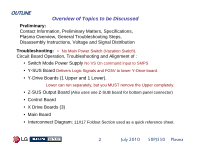
, Preliminary Matters, Specifications, Plasma Overview, General Troubleshooting Steps, Disassembly Instructions, Voltage and Signal Distribution Troubleshooting: • No Main Power Switch (Vacation Switch). Circuit Board Operation, Troubleshooting and Alignment of : • Switch Mode Power Supply No VS On - LG 50PJ340 | Training Manual - Page 3
Overview of Topics to be Discussed 50PJ350 Plasma Display The first section will cover Contact Information and Important Safety Precautions for the Customers Safety as well as the Technician and the Equipment. Basic Troubleshooting Techniques which can save time and money sometimes can be overlooked - LG 50PJ340 | Training Manual - Page 4
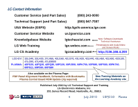
Contact Information Customer Service (and Part Sales) (800) 243-0000 Technical Support (and Part Sales) (800) 847-7597 USA Website (GSFS) http://gsfs-america.lge.com Customer Service Website us.lgservice.com Knowledgebase Website LG Web Training LG CS Academy lgtechassist.com lge.webex.com - LG 50PJ340 | Training Manual - Page 5
performing the necessary checks. Also be aware that many household products present a weight hazard. At least two people should be involved in the installation or servicing of such devices. Failure to consider the weight of an product could result in physical injury. 5 July 2010 50PJ350 Plasma - LG 50PJ340 | Training Manual - Page 6
Class B digital device, pursuant to Part 15 of the FCC Rules. These and used in accordance with the instruction manual, may cause harmful interference to turning the equipment off and on, the user is encouraged to try to correct the interference TV technician for help. 6 July 2010 50PJ350 Plasma - LG 50PJ340 | Training Manual - Page 7
making adjustments on the Power Supply, Y-SUS and Z-SUS part number accuracy. 2. Check the model label. Verify model names and board model matches. 3. Check details of defective condition and history. Example: Y-SUS or Y-Drive Board Failure, Mal-discharge on screen, etc. 7 July 2010 50PJ350 Plasma - LG 50PJ340 | Training Manual - Page 8
parts and check for possible overheated components. Capacitors will sometimes leak dielectric material and give off a distinct odor. Frequency of power supplies The final step is to correct the problem. Be careful of ESD and make sure to check the DC Supplies for proper levels. Make all necessary - LG 50PJ340 | Training Manual - Page 9
50PJ350 PRODUCT INFORMATION SECTION This section of the manual will discuss the specifications of the 50PJ350 Advanced Single Scan Plasma Display Television. 9 July 2010 50PJ350 Plasma - LG 50PJ340 | Training Manual - Page 10
50PJ350 Specifications 1080P PLASMA HDTV 50" Class (50" diagonal) • 600Hz Sub Field Driving • High Definition Resolution • 3M:1 Dynamic Contrast Ratio • TruSlim Frame • Picture Wizard II (Easy Picture Calibration) • Smart Energy Saving • Intelligent Sensor • Dual XD™ Engine • AV Mode(Cinema, Sports - LG 50PJ340 | Training Manual - Page 11
50PJ350 Logo Familiarization Page 1 of 3 600Hz Sub Field Firing: Capture every moment. Tired less than 1" thick the new TruSlim Frame trims away distraction without compromising screen size. USB 2.0: View videos and photos and listen to music on your TV through USB 2.0. 11 July 2010 50PJ350 Plasma - LG 50PJ340 | Training Manual - Page 12
50PJ350 Logo Familiarization Page 2 of 3 HD RESOLUTION 720P HD Resolution Pixels: 1365 (H) × 768 (V) See and experience more. Pictures are sharper. Colors are more vibrant. Entertainment is more real. Everything looks better on an HDTV. HDMI (1.3 Deep Color) Digital multi-connectivity HDMI (1.3 - LG 50PJ340 | Training Manual - Page 13
high-quality dialogue when background noise swells. Save Energy, Save Money It reduces the plasma display's power consumption. The default factory same price as less-efficient models. Less energy means you pay less on your energy bill. Draws less than 1 Watt in stand by. 13 July 2010 50PJ350 Plasma - LG 50PJ340 | Training Manual - Page 14
process (vs. Comp. 8 sub-field/frame) • No smeared images during fast motion scenes Original Image 10 Sub Fields Per Frame Sub Field firing occurs using wall charge and polarity differences between Y-SUS and Z-SUS signals. 14 July 2010 50PJ350 Plasma - LG 50PJ340 | Training Manual - Page 15
50PJ350 Remote Control p/n AKB72914201 TOP PORTION BOTTOM PORTION 15 July 2010 50PJ350 Plasma - LG 50PJ340 | Training Manual - Page 16
50PJ350 Rear and Side Input Jacks REAR INPUTS AC In USB for Music, Photos and Software Upgrades SIDE INPUTS USB HDMI 3 Composite Video/Audio 16 July 2010 50PJ350 Plasma - LG 50PJ340 | Training Manual - Page 17
2-3/16" 55.88mm 30-13/16" 782.32mm 28-3/8" 721.36mm Model No. Serial No. Label 2-3/8" 60.96mm Weight: 78.5 lbs with Stand 60.8 lbs without Stand 15-3/4" 400mm Remove 4 screws to remove stand for wall mount 20-7/8" 530mm 17 7-3/8" 187.2mm 2-3/4" 70mm 12-3/16" 309.88mm July 2010 50PJ350 Plasma - LG 50PJ340 | Training Manual - Page 18
DISASSEMBLY SECTION This section of the manual will discuss Disassembly, Layout and Circuit Board Identification, of the 50PJ350 Advanced Single Scan Plasma Display Panel. Upon completion of this section the Technician will have a better understanding of the disassembly procedures, the layout of - LG 50PJ340 | Training Manual - Page 19
Removing the Back Cover To remove the back cover, remove the 32 screws Indicated by the arrows. (The Stand does not need to be removed). PAY CLOSE ATTENTION TO THE TYPE, SIZE AND LENGTH Of the screws when replacing the back cover. Improper type can damage the front. 19 July 2010 50PJ350 Plasma - LG 50PJ340 | Training Manual - Page 20
Soft Touch Keyboard FPC Identifying the Circuit Boards Panel Voltage and Panel ID Label Power Supply (SMPS) Control AC In Center "X" Conductive Tape Invisible Speakers FPC Z-SUS Z-SUB Main Board Right "X" FPC FPC Side Input (part of main) Conductive Tape 20 July 2010 50PJ350 Plasma - LG 50PJ340 | Training Manual - Page 21
P204 Y-SUS Board p/n: EBR63039801 P205 P212 P101 P203 Y-DRIVE LOWER Board P812 SMPS POWER SUPPLY Board Top row Odd Back row Even p/n: EAY60968701 SC101 LN P813 P111 P102 n/c EBR65007704 Front "Soft Switch" Key Pad p/n: EAB60962801 Speakers (Front Left) 21 July 2010 50PJ350 Plasma - LG 50PJ340 | Training Manual - Page 22
semiconductors are CMOS and prone to static failure. Switch Mode Power Supply Board Removal Disconnect the following connectors: P812, P813 and Drive Board. Collar Note: Y-SUS, Z-SUS and Y-Drive boards are mounted on board stand-offs that have a small collar. The board must be lifted slightly - LG 50PJ340 | Training Manual - Page 23
screws in the Z-SUB board. Lift up slightly to clear the screw stand-offs and pull the Z-SUS to the left. Unseat P3/P7 from from the two metal supports at the bottom and Remove the board. Front IR and Key Pad Removal FRONT IR/INTELLIGENT SENSOR and POWER BUTTON: Disconnect P100 and 50PJ350 Plasma - LG 50PJ340 | Training Manual - Page 24
flex the panel glass. a) Remove the Back Cover. b) Remove the Stand (4 Stand Screws were removed during back removal). c) Remove the Stand Metal Support Bracket (5 Screws) 2 Plastic tap thread and 3 Metal thread. d) reverse order. Recheck Va / Vs / VScan / -VY / Z-Drive. 24 July 2010 50PJ350 Plasma - LG 50PJ340 | Training Manual - Page 25
Getting to the X Circuit Boards D Left With Stand removed C D Right Warning: Never run the TV with the TCP Heat Sink removed E Heat Sink Ground Wire C B Warning Shorting Hazard: Conductive Tape. Do not allow to touch energized circuits. 25 July 2010 50PJ350 Plasma - LG 50PJ340 | Training Manual - Page 26
TCP upward on all TCP connectors Left X: P101~108 Center X: P201~207 Right X: P301~308 Cushion (Chocolate) 26 Example Flexible ribbon cable connector July 2010 50PJ350 Plasma - LG 50PJ340 | Training Manual - Page 27
ribbon cable. Tab Separate the TCP from the connector as shown. TCP Film can be easily damaged. Handle with care. Tab Tab 27 July 2010 50PJ350 Plasma - LG 50PJ340 | Training Manual - Page 28
between boards) The Left X Board drives the Right 5/16 of the side of the screen vertical electrodes The Center X Board drives the Center 3/8 of the of the screen vertical electrodes The Right X Board drives the Left 5/16 of the side of the screen vertical electrodes 28 July 2010 50PJ350 Plasma - LG 50PJ340 | Training Manual - Page 29
AND CIRCUIT ALIGNMENT SECTION 50PJ350 Plasma Display This Section will cover Circuit Operation, Troubleshooting and Alignment of the Power Supply, Y-SUS Board, Y-Drive Boards, Z-SUS Board, Control Board, Main Board and the X Drive Boards. At the end of this Section the technician should - LG 50PJ340 | Training Manual - Page 30
50PJ350 Signal and Voltage Distribution Block Y Drive Upper FPCs 5VFG (5V) measured from Floating Ground 15VFG (15V) measured from Floating Ground SMPS TURN ON SEQUENCE Step 1: RL_ON: 17V, 5V, AC_Det, Error Det, Step 2: M_On: M5V, Va, Vs SMPS OUTPUT VOLTAGES IN STBY STB +5V SMPS OUTPUT Stand Power - LG 50PJ340 | Training Manual - Page 31
Set Up / -Vy / Vsc / Ve / Vzb) (6) Trade name of LG Electronics (7) Manufactured date (Year & Month) (8) Warning (9) TUV Approval Mark (Not Used) (10) UL Approval Mark (11) UL Approval No. (12) Panel Model Name (13) Max. Watt (Full White) (14) Max. Volts (15) Max. Amps 31 July 2010 50PJ350 Plasma - LG 50PJ340 | Training Manual - Page 32
Remember, the Voltage Label MUST be followed, it is specific to the panel's needs. Power Supply The Waveform adjustment is only necessary 1) When the Y-SUS board is replaced 2) When a "Mal-Discharge" problem is encountered 3) When an abnormal picture issues is encountered Set-Up -Vy Vsc Ve ZBias - LG 50PJ340 | Training Manual - Page 33
in this panel. SMPS p/n: EAY60968701 Check the silk screen label on the top center of the Power Supply board to identify the correct part number. (It may vary in your specific model number). On the following pages, we will examine the Operation of this Power Supply. 33 July 2010 50PJ350 Plasma - LG 50PJ340 | Training Manual - Page 34
TV in 10 seconds) and Error_Det (not used) Adjustments There are 2 adjustments located on the Power Supply Board VA and VS. The M5V is pre-adjusted and fixed. All adjustments are made referenced to Chassis Ground. Use "Full White Raster" 100 IRE VS VR901 VA VR502 34 July 2010 50PJ350 Plasma - LG 50PJ340 | Training Manual - Page 35
Power Supply Board Layout (Drawing) P812 VA TP VS TP F801 4A 250V Stand-By: 0.9V Run: 388V VS and VA TP ZD803 D805 T901 SMPS p/n: EAY60968701 T902 VR901 VS Adj VR502 VA Adj ZD302 D609 ZD401 D601 D307 ZD301 ZD303 D601 D303 ZD101 D305 Stand-By: 1.5V Run: 388V L601 D308 D309 D306 D302 - LG 50PJ340 | Training Manual - Page 36
Power Supply Circuit Layout P812 Primary Source VS VR901 To Y-SUS Fuse F801 0.9V Stby 388V Run 4Amp/250V VS Source VA Source Fuse F302 1.5V Circuit Bridge Rectifier STBY 5V, RL104 RL103 5V Source N/C To MAIN 10Amp/250V 36 Main Fuse F101 AC Input SC 101 P813 July 2010 50PJ350 Plasma - LG 50PJ340 | Training Manual - Page 37
) on the Main Board receives a "POWER ON" Command from either the Power button or the Remote IR Signal, it outputs a high (2.43V) called RL_ON at power supply in stages automatically. A load is necessary to perform a good test of the SMPS if the Main board is suspect. 37 July 2010 50PJ350 Plasma - LG 50PJ340 | Training Manual - Page 38
50PJ350 POWER SUPPLY START UP SEQUENCE F302 In Stand-By Primary side is 1.5V In Run (Relay On) Primary side is 388V F801 POWER SUPPLY 7 AC In Stand-By 0.9V Run 388V (SMPS) 1 Stand AC By 5V Reg Det STBY RUN +5V 9 Regulator 5 17V 3.46V 5.14V Reg 8 M5V M5V Reg Vs Vs Reg Va Va 9 7 Reg 8 - LG 50PJ340 | Training Manual - Page 39
Power Supply Board Layout (Drawing) P812 VA TP VS TP F801 4A 250V Stand-By: 0.9V Run: 388V VS and VA TP ZD803 D805 T901 SMPS p/n: EAY60968701 T902 VR901 VS Adj VR502 VA Adj ZD302 D609 ZD401 D601 D307 ZD301 ZD303 D601 D303 ZD101 D305 Stand-By: 1.5V Run: 388V L601 D308 D309 D306 D302 - LG 50PJ340 | Training Manual - Page 40
OK. Note: To be 100% sure, you would need to read the current handling capabilities of each power supply listed on the silk screen on the SMPS and place each supply voltage under the appropriate load. 100W 100W Pins 1 or 2 VS Gnd Pins 4 or 5 or 8 P812 VA VS Test Points F801 4A 250V T901 - LG 50PJ340 | Training Manual - Page 41
50PJ350 Power Supply Troubleshooting With P813 disconnected capabilities of each power supply listed on the silk screen on the SMPS and place each supply voltage under the appropriate load. Then follow the instructions below to completely pins 9 and 10). 100Ω 100Ω 41 July 2010 50PJ350 Plasma - LG 50PJ340 | Training Manual - Page 42
RL_On command arrives. b Note: The M5V, Va and Vs turn on when the M_On (Monitor On) command arrives. c Note: The Error Det line is not used in this model. d Note: If the AC Det line is Missing, the TV will shut off after 10 seconds of operation. e Note: Pin 18 is grounded on - LG 50PJ340 | Training Manual - Page 43
Voltages and Diode Check SC101 AC INPUT Connector SC101 Pin Number L and N Standby 120VAC Run 120VAC Diode Mode Open P812 P812 "Power Supply" to Y-SUS "P210" Va TP 1 Vs TP Pin 1, 2 3 4, 5 6, 7 8 9, 10 Label *Vs all connectors Disconnected. DVM in Diode Mode. 43 July 2010 50PJ350 Plasma - LG 50PJ340 | Training Manual - Page 44
of the Presentation will cover alignment and troubleshooting the Y-SUS Board for the Single Scan Plasma. Upon completion of the Section the Supplied Y-SUS Developed Floating Ground VA VS M5V VA supplies the Panel's Vertical Electrodes (Routed to the Left X-Board) VS Supplies 2010 50PJ350 Plasma - LG 50PJ340 | Training Manual - Page 45
Y-SUS Block Diagram Power Supply Board - SMPS Distributes Vs Simplified Block Diagram of Y-Sustain Board Distributes Vs, Va and M5V Y-SUS Board VA Receive panel Y-Drive Boards Receive Scan Waveform Display Panel Logic signals needed to generate drive waveform 45 July 2010 50PJ350 Plasma - LG 50PJ340 | Training Manual - Page 46
for Z-SUS M5V (pins 4-7) VR501 VSC c VR502 -Vy P101 P203 c Va to Left X Board Pins 5~7 46 July 2010 Ribbon Logic Signals from the Control Board 50PJ350 Plasma - LG 50PJ340 | Training Manual - Page 47
50PJ350 Y-SUS Layout Drawing Example: Model : PDP 50T1### Voltage Setting: 5V/ Va:60/ Vs:206 FG N.A. / -198 / 135 / N.A. / 95 Max Watt : 330 W (Full White) -Vy 01V 1.14V 27 YER_UP 0.62V 1.14V 28 Y_Pass_Top 1.08V 1.14V 29 YSUS_UP 0.06V 1.14V 30 Gnd Gnd Gnd 47 July 2010 50PJ350 Plasma - LG 50PJ340 | Training Manual - Page 48
Adjustments This is just for example Set should run for 15 minutes, this is the "Heat Run" mode. Set screen to "White Wash". 1) Adjust -Vy VR502 to Panel's Label voltage (+/- 1V) 2) Adjust VSC VR501 to Panel Adj Location: Bottom Center of board Just above Transformer 48 July 2010 50PJ350 Plasma - LG 50PJ340 | Training Manual - Page 49
right in the screen picture. e Highlighted signal from waveforms above observed 100uS/div There are several other test points on either the Upper or Lower Y-Drive boards that can be used. Basically any output pin on any of the FPC to the panel are OK to use. 49 100uSec July 2010 50PJ350 Plasma - LG 50PJ340 | Training Manual - Page 50
Locking on to the Y-Drive Waveform Tip Note, this TP (VS_DA) can be used as an External Trigger for scope when locking onto the Y-Drive (Scan) or the Z-Drive signal. This signal can also be used to help lock the scope when observing the LVDS video signals. 50 July 2010 50PJ350 Plasma - LG 50PJ340 | Training Manual - Page 51
if you use the "Expanded" mode of your scope. Area for Set-Up adjustment Area for Set-Dn adjustment 51 224V p/p 180 uSec July 2010 50PJ350 Plasma - LG 50PJ340 | Training Manual - Page 52
be in "WHITE WASH" All other DC Voltage adjustments should have already been made. Observe the Picture while making these adjustments. Normally, they do not have to be done. ADJUSTMENT LOCATION: Top Left time of the signal to match the waveform above. (180uSec ± 5uSec) July 2010 50PJ350 Plasma - LG 50PJ340 | Training Manual - Page 53
Set Up Adjustment Too High or Low Set Up swing is Minimum 181V Max 266V p/p 53 July 2010 50PJ350 Plasma - LG 50PJ340 | Training Manual - Page 54
Set Down Adjustment Too High or Low Set Dn swing is Minimum 116uSec Max 205uSec Normal 180uSec 23V off the Floor Floor Too Low 116uSec 54 July 2010 50PJ350 Plasma - LG 50PJ340 | Training Manual - Page 55
boards. This Section of the Presentation will cover troubleshooting the Y-SUS Board. Warning: Never run the Y-SUS with P212 (Y-SUS) or P204/P110 (Y-Drives) removed unless the Y-Drive boards are removed completely. Board Failure will occur. P/N EBR6303801 Scan Scan 55 July 2010 50PJ350 Plasma - LG 50PJ340 | Training Manual - Page 56
(4.9V) measured from Pins 15 or 16 To Floating Gnd Use screw just above P212 on the Y-SUS c Y-Drive Lower Y-SUS Board 56 July 2010 50PJ350 Plasma - LG 50PJ340 | Training Manual - Page 57
Floating Gnd TP without an Isolation Transformer. All logic pins about (400V p/p) Pins 3~12 are Logic (Drive) Signals to the Y-Drive Upper. 57 July 2010 50PJ350 Plasma - LG 50PJ340 | Training Manual - Page 58
3 YB_OC2 2.63V 1.47V 0.68V 2 SUS_DN (FG) FG FG FG Y-Drive Board should be disconnected for this test. 1 SUS_DN (FG) FG FG FG 58 July 2010 50PJ350 Plasma - LG 50PJ340 | Training Manual - Page 59
are on the back of the board. To Test these voltages, remove the board completely, supply Ground and any 5V supply to M5V fuse FS202. P118 D511 FG 19.86V FG 15V Regulator IC508 Floating Ground checks must IC508 Bottom Leg. Location Location Back Side of Board 59 July 2010 50PJ350 Plasma - LG 50PJ340 | Training Manual - Page 60
at Cathode Side D515. Standby: 0V Run: 16V Diode Check: 1.32V Location T502 D515 16V Source Cathode Right Side Just above T502 60 July 2010 50PJ350 Plasma - LG 50PJ340 | Training Manual - Page 61
Disconnected or Connected FS201 (M5V) 10V/125V Diode Check 1.19V With Board Disconnected. 0.97V with board connected. 16V Pins 1 through 3 M5V Pins 4 through 7 July 2010 50PJ350 Plasma - LG 50PJ340 | Training Manual - Page 62
Y-SUS P113 and P114 Plug Information Voltage and Diode Mode Measurement P210 Connector "Y-SUS" to "Power Supply" P812 Pin Label Run Diode Check 1~2 Vs *195V Open 3 n/c n/c n/c 4~5 Gnd Gnd Gnd 6~7 Va * all connectors Disconnected. DVM in Diode Mode. 62 July 2010 50PJ350 Plasma - LG 50PJ340 | Training Manual - Page 63
c * Note: These voltages will vary in accordance with Panel Label Diode Mode Readings taken with all connectors Disconnected. DVM in Diode Mode. 63 July 2010 50PJ350 Plasma - LG 50PJ340 | Training Manual - Page 64
0.95V 1.01V 0.62V 1.08V 0.06V Gnd Diode 1.02V 1.14V 1.14V 1.14V 1.14V 1.14V 1.14V 1.14V 1.14V 1.14V 1.14V 1.14V 1.14V 1.14V Gnd There are No Stand By Voltages on this Connector c Diode Mode Readings taken with all connectors Disconnected. DVM in Diode Mode. 64 July 2010 - LG 50PJ340 | Training Manual - Page 65
UPPER (TOP) Y-DRIVE LOWER (BOTTOM) Y-Drive Boards work as a path supplying the Sustain and Reset waveforms which are made in the Y-Sustain board and is synchronized by receiving Logic scan signals from the Control board. The 50PJ350 uses 8 Driver ICs on 2 Y-Drive Boards commonly called "Y-Drive Buffers" - LG 50PJ340 | Training Manual - Page 66
boards operate from Floating Ground, (no reference to Chassis Gnd). Floating Gnd 5V can be measured across C105 (Upper) or C205 (Lower). 66 July 2010 50PJ350 Plasma - LG 50PJ340 | Training Manual - Page 67
Y-SUS SIDE p/n: EBR63551601 Y-Drive signal (VSC), FG5V Volts from the Y-SUS board and Logic Signals from the Control board through the Y-SUS are supplied to the Lower Y-Drive Board on Connector P205. Floating Ground Standoff The Floating Ground Standoff delivers FG To the Y-Drive Boards. There are - LG 50PJ340 | Training Manual - Page 68
lugs. FG5V Volts from the Y-SUS board and Logic Signals from the Control board through the Y-SUS are supplied to the Lower Y-Drive Board on Connector P205. P204 delivers these same signals to the Upper Y-Drive P204 FG To the Y-Drive Boards. There are 2 per/board. 68 July 2010 50PJ350 Plasma - LG 50PJ340 | Training Manual - Page 69
Scan Signal FL201 FG5V Fuse Scan Signal Any Connector to the Panel (Buffer Output TP) Diode Mode Reading from Floating Ground Scan Signal TP Open with Red Lead 0.41V with Black Lead on Scan Floating Gnd Any Output Buffer TP Open with Red Lead on Scan 0.79V with Black Lead on Scan 69 July 2010 - LG 50PJ340 | Training Manual - Page 70
Open Indicated by white outline Any of these output lugs can be tested. Look for shorts indicating a defective Buffer IC 6 Ribbon cables communicating with the Panel's (Horizontal Electrodes) totaling 768 lines determining the Panel's Vertical resolution pixel count. 70 July 2010 50PJ350 Plasma - LG 50PJ340 | Training Manual - Page 71
FG Open 0.53V 0.55V 0.52V 0.52V 0.52V FG 0.41V FG Diode Mode Readings taken with all connectors Disconnected. DVM in Diode Mode. 71 July 2010 50PJ350 Plasma - LG 50PJ340 | Training Manual - Page 72
FG 0.41V FG 0.52V 0.52V 0.52V 0.55V 0.53V Open FG Diode Mode Readings taken with all connectors Disconnected. DVM in Diode Mode. 72 July 2010 50PJ350 Plasma - LG 50PJ340 | Training Manual - Page 73
or Lower Flexible Ribbon Cables shown are from a different model, but process is the same. To remove the Ribbon lift from under the tab as shown in Fig 1). The locking tab must be standing straight up as shown in Fig 2. Lift up the entire Ribbon Cable gently Fig 1). 73 July 2010 50PJ350 Plasma - LG 50PJ340 | Training Manual - Page 74
. In this case the Tab on the Ribbon cable was improperly seated at the top. This can cause bars, lines, intermittent lines abnormalities in the picture. Remove the ribbon cable and re-seat it correctly. 74 July 2010 50PJ350 Plasma - LG 50PJ340 | Training Manual - Page 75
test points needed for troubleshooting and all alignments. Note: The Z-SUS can not be run "Stand-Alone" in the 50T1 Panel Models. Locations • DC Voltage and Waveform Test Points • Z BIAS Alignment • Diode Mode Test Points Operating Voltages Power Supply Supplied VS M5V Routed through Control - LG 50PJ340 | Training Manual - Page 76
Z-SUS Block Diagram M5V and VS Y-SUS Board 16V M5V Control Board Power Supply Board VS M5V 16V Z-SUS board receives VS and M5V SMPS and 17V from the Control board FET Makes Drive waveform Simplified Block Diagram of Z-SUS (Sustain) Board Z-SUB PDP Display Panel 76 July 2010 50PJ350 Plasma - LG 50PJ340 | Training Manual - Page 77
the Y-SUS generates +16V. M5V and 16V are routed through the Control board. Logic Signals generated on the Control board. 77 No IPMs P101 Z-SUS Output FETs No IPMs Z-SUS Waveform Test Point J36 P102 P3 To Z-SUB July 2010 50PJ350 Plasma - LG 50PJ340 | Training Manual - Page 78
50PJ350 Z-SUS Layout Drawing FS1 VS D309 4A / 250V D312 P2 Z-SUS BOARD p/n: EBR63040301 VZB TP P1 VR201 VZB P4 Z-Bias Waveform J36 P5 P3 78 July 2010 50PJ350 Plasma - LG 50PJ340 | Training Manual - Page 79
for generating SUSTAIN and DISCHARGE in the Panel. This waveform is supplied to the panel through two FPC (Flexible Printed Circuit) connections P101 Reset Y Drive Waveform Oscilloscope Connection Point. J36 to check Z Output waveform. Right Hand Side Center. Z Drive Waveform (Vzb) 50PJ350 Plasma - LG 50PJ340 | Training Manual - Page 80
Left of Z-SUS Board VZB (Z Bias) + - VZB (Z-Bias) TP VZB (Z Bias) VR201 Set should run for 15 minutes, this is the "Heat Run" mode. Set screen to "White Wash" mode or 100 IRE White input. All SMPS adjustments should have been completed. 1. Place DC Volt meter between VZB TPs. 2. Adjust VZB - LG 50PJ340 | Training Manual - Page 81
to Y-SUS P211 Voltages and Diode Checks Voltage and Diode Mode Measurements P2 Location: Top Left There are no Stand-By voltages on this connector P2 "Z-SUS" to "Y-SUS" P211 Pin Label Run 1~2 Gnd Gnd 3 with all connectors Disconnected. DVM in Diode Mode. 81 July 2010 50PJ350 Plasma - LG 50PJ340 | Training Manual - Page 82
12 Gnd Gnd Diode Check Open 1.52V Gnd 3.09V Open Open Open Open Open Gnd P1 Location: Bottom Left hand side Pin 1 There are no Stand-By voltages on this connector Diode Mode Readings taken with all connectors Disconnected. DVM in Diode Mode. 82 July 2010 - LG 50PJ340 | Training Manual - Page 83
points needed for troubleshooting. Signals • DC Voltage and Waveform Test Points • Diode Mode Test Points Main Board Supplied Panel Control and Signals (Sustain) X Board Drive Signals (RGB Address) Operating Voltages Y-SUS Supplied +5V (M5V) Developed on the SMPS +16V (Routed to the Z-SUS - LG 50PJ340 | Training Manual - Page 84
Control Board Pictorial n/c (For ROM Updates) P102 P111 IC231 P121 p/n: EBR63549501 IC211 P101 IC801 P161 Pattern Generator For Panel Test D201 Should be blinking P162 84 July 2010 50PJ350 Plasma - LG 50PJ340 | Training Manual - Page 85
unit on, if D201 is not on, check 5V supply from FS202 on the Y-SUS. Pins 4~7 of P111 LVDS Cable. Short across Auto Gen TPs to generate a test pattern. When A/C power is applied. To Test Control Board: Disconnect all connectors. Jump STBY 5V from SMPS (2) 1.8V (3) 3.27V 85 July 2010 50PJ350 Plasma - LG 50PJ340 | Training Manual - Page 86
not only protects the panel from overheating, but it also is responsible for manipulating the Y-Drive waveform as the panel changes temperature. 86 July 2010 50PJ350 Plasma - LG 50PJ340 | Training Manual - Page 87
Locking on to the Y-Drive or Z-Drive Waveform Tip Note, this TP (VS_DA) can be used as an External Trigger for scope when locking onto the Y-Drive (Scan) or the Z-Drive signal. This signal can also be used to help lock the scope when observing the LVDS video signals. 87 July 2010 50PJ350 Plasma - LG 50PJ340 | Training Manual - Page 88
Board Check the output of the Oscillator (Crystal) X101. The frequency of the sine wave is 25 MHZ. Missing this clock signal will halt operation of the panel drive signals. Osc. Check: 25Mhz Left Leg X101 Osc. Check: 25Mhz Right Leg CONTROL BOARD CRYSTAL LOCATION 88 July 2010 50PJ350 Plasma - LG 50PJ340 | Training Manual - Page 89
Signal (Simplified Block Diagram) The Control Board supplies Video Signals to the TCP (Tape Carrier Package) ICs. If there is a bar defect on the screen, it could be a Control Board problem. Control Board to X Board Address Signal Flow This Picture shows Signal Flow Distribution to help determine - LG 50PJ340 | Training Manual - Page 90
Pins 4 through 7 Receive M5V from the Y-SUS. Protected on Y-SUS by FS202 Pin c P111 Label Silk Screen All the rest are delivering Y-SUS Waveform development and Y-Drive logic signals to the Y-SUS Board (Y-Drive logic Pins 1~2. The M5V also leaves on P101 Pins 3~4. 90 July 2010 50PJ350 Plasma - LG 50PJ340 | Training Manual - Page 91
Control P111 to Y-SUS P101 Plug Information Note: There are no voltages in Stand-By mode P111 "Control" Odd Pins to P101 "Y-SUS" Pin Label Run Diode Check 1 +15V 16V Open 3 +15V 16V with all connectors Disconnected. Black lead on Gnd. DVM in Diode Mode. 91 July 2010 50PJ350 Plasma - LG 50PJ340 | Training Manual - Page 92
The video is delivered in 12 bit LVDS format. Their presence can be confirmed with the Oscilloscope by monitoring the LVDS signals with SMPTE Color Bar input. Loss of these Signals would confirm the failure is on . Pins 9~10 and 22~23 are clock signals for the data. 92 July 2010 50PJ350 Plasma - LG 50PJ340 | Training Manual - Page 93
to use the EX_AUTO_GEN shorting pins to create multiple internal generated test patterns (Panel Test). Enables the Control Board Note: There are no voltages in Stand-By mode. 93 July 2010 50PJ350 Plasma - LG 50PJ340 | Training Manual - Page 94
Connector Pin ID and Voltages Voltage and Diode Mode Measurements for the Control Board. Note: There are no voltages in Stand-By mode. P101 Label P101 Connector "Control" to "Z-SUS Board" P1 Pin Label Run Diode Check 1 (+ . Black lead on Gnd. DVM in Diode Mode. 94 July 2010 50PJ350 Plasma - LG 50PJ340 | Training Manual - Page 95
0.97V 1.27V 0.97V 1.0V 0.97V 1.27V 0.97V 1.87V 1.2V 1.87V 1.2V 3.22V 1.2V 0.49V 1.1V 0.49V 1.1V 95 July 2010 White hash marks count as 5 50PJ350 Plasma - LG 50PJ340 | Training Manual - Page 96
1.27V 1.0V 1.27V 1.0V 1.27V 1.0V 1.27V 3.3V Diode Mode 0.97V 0.97V 1.2V 1.2V 1.2V 1.1V 0.97V 0.97V 0.67V Note: There are no voltages in Stand-By mode. 96 July 2010 50PJ350 Plasma - LG 50PJ340 | Training Manual - Page 97
these FPCs. These boards have no adjustment. X-BOARD OPERATIONAL VOLTAGE: • VA: Originally developed on the Switched Mode Power Supply. VA (Voltage for Address) is routed through the Y-SUS board, out on P203 pins 5~7 and then to via P211 pins 11~12 to P331 pins 41~42. 97 July 2010 50PJ350 Plasma - LG 50PJ340 | Training Manual - Page 98
of 16 TCPs and each TCP has 2 gate arrays, so there are a total of 32 buffers feeding the panel's 4986 vertical electrodes. 98 July 2010 50PJ350 Plasma - LG 50PJ340 | Training Manual - Page 99
X Board TCP Heat Sink Warning NEVER run the television with this heat sink removed. Damage to the TCPs will occur and cause a defective panel. The Vertical Address buffers (TCPs) have one heat sink indicated by the arrow. It protects all 16 TCPs. 99 July 2010 50PJ350 Plasma - LG 50PJ340 | Training Manual - Page 100
: On any Va (Open) TCPs connected. On any Va (Open) TCPs disconnected. On 3.3V (1.9V) TCPs connected. On 3.3V (2.5V) TCPs connected. 100 July 2010 50PJ350 Plasma - LG 50PJ340 | Training Manual - Page 101
Taped Carrier Package Connector FCleaxbilbele Long Black Heat Sink 101 256 total lines Chocolate 128 lines 128 lines Back side of TCP Ribbon July 2010 50PJ350 Plasma - LG 50PJ340 | Training Manual - Page 102
TCP Testing Va: P122 5~7 from Y-SUS Va: Routes to: 50PJ350 X Board TCP Connector Distribution Any X Board to Any TCP P101~P105 or P201~P206 or P301~P305 Leaves 35 40 45 50 Look for any TCPs being discolored. Ribbon Damage. Cracks, folds Pinches, scratches, etc... 102 July 2010 50PJ350 Plasma - LG 50PJ340 | Training Manual - Page 103
. Example here from P204. You can only check for continuity back to IC231, you can not run the set with heat sink removed. July 2010 50PJ350 Plasma - LG 50PJ340 | Training Manual - Page 104
can, (at the location of the TCP). a) Cause the Power Supply to shutdown. (VA shorted, 3.3V shorted). b) Generate abnormal vertical bars, (colored noise). c) Cause the entire area driven by the TCP to be " Tapped Carrier Package Look for burns, pin holes, damage, etc. 104 July 2010 50PJ350 Plasma - LG 50PJ340 | Training Manual - Page 105
from Y-SUS P203 Information Voltage and Diode Mode Measurement (No Stand-By Voltages) P122 "X Drive Left" to "Y-SUS" P203 Pin Note: This voltage will vary in accordance with Panel Label. There are no Stand-By voltages on this connector. Diode Mode Readings taken with all connectors Disconnected - LG 50PJ340 | Training Manual - Page 106
(Open) all connectors removed, TCPs disconnected. On Va (0.55) Y-SUS connector removed, TCPs connected. On Va (0.6V) all connectors removed, TCPs disconnected. 106 July 2010 50PJ350 Plasma - LG 50PJ340 | Training Manual - Page 107
the Microprocessor, Audio section, video section and all input, outputs. It also STAND-BY: From SMPS • STBY 5V DURING RUN From SMPS : (STBY 5V remains): • +5V for Video processing • 16V for Audio Power LEDs. • Distributes +3.3V_ST and +3.3V_MST to the Front IR Board. 107 July 2010 50PJ350 Plasma - LG 50PJ340 | Training Manual - Page 108
Main Board Layout and Identification P704 to Ft IR P301 to SMPS P703 LVDS P801 Audio Optical Audio PC Audio HDMI Remote PC IC1 Microprocessor Video Processor RS232 USB HDMI Rear Inputs 108 RF In July 2010 50PJ350 Plasma - LG 50PJ340 | Training Manual - Page 109
50PJ350 Main Front Layout Drawing P704 To SMPS P301 To Ft IR L803 IC801 P801 L804 To SPK (All Pins 12.3V) C C A1 A2 D2 D1 A1D504 P703 IC308 L313 X402 25Mhz IC402 31.875Mhz X401 IC401 Tuner Q404 Q402 EB C C E BB E C C BE D505 A1 A2 C Q401 Q403 109 July 2010 50PJ350 Plasma - LG 50PJ340 | Training Manual - Page 110
Main Board Front Side Component Voltages 50PJ350 Main Board (Front Side) Component Voltages IC202 7V (to IC405) Pin Regulator [1] Gnd [2] Gnd [3] Gnd [4] Gnd [5] 3.3V [6] 3.3V [7] Gnd [8] 3.3V IC308 1.3V_VDDC Pin Regulator Use - LG 50PJ340 | Training Manual - Page 111
50PJ350 Main Back Layout Drawing IC701 IC501 IC301 3 1 2 IC203 Q504 EB C IC504 IC306 3 1 2 3 1 2 IC307 IC304 2 1 3 Q303 S GE B DC Q304 C B Q301 SG D Q302 3 1 2 IC303 IC703 D502 A2 A1 C Q501 E C B IC502 Q702 CE B Q503 E C B IC503 IC602 July 2010 50PJ350 Plasma - LG 50PJ340 | Training Manual - Page 112
50PJ350 Main Board Back Side Component Voltages IC203 Winbond Serial Pin Flash [1] 0V [2] 3.30V [3] n/c [4] n/c [5] n/c [6] n/c [7] 0V [8] 3.3V [9] 0V [10] Gnd [11] n/c [12] n/c [13] n/c [14] n/c [15] 0V [16] - LG 50PJ340 | Training Manual - Page 113
Main Board Tuner Explained The Tuner in this set is discreet components (Silicon Tuner) and no longer a self contained unit (can). Check for Tuner B+: 3.3V on IC306 and 1.8V on IC307 Back Side bottom left hand side Front bottom right hand side 113 July 2010 50PJ350 Plasma - LG 50PJ340 | Training Manual - Page 114
Left Side 2.6V p/p Right Side 3.50V p/p X402 25MHZ Top Side 2.8V p/p Bottom Side 4.2V p/p X401 31.875MHZ Left Side 0.7V p/p Right Side 1V p/p July 2010 50PJ350 Plasma - LG 50PJ340 | Training Manual - Page 115
Main Board Removing the LVDS Cable or Power Supply Connector (1) Using your fingers and press in gently on the two locking tabs. Then rock the connector out of the plug use a thin object and slide straight down (as indicated by the arrows below) and release the locks. 115 July 2010 50PJ350 Plasma - LG 50PJ340 | Training Manual - Page 116
/div Pin 12 10uSec per/div Pin 11 2uSec per/div Pin 12 2uSec per/div MAIN Board Main Board P703 Location 116 July 2010 50PJ350 Plasma - LG 50PJ340 | Training Manual - Page 117
row right side Note: There are no wires into pins 1 and 2. Blue Pins indicate 10 bit differential video signal Note: There are no voltages in Stand-By mode. Diode Mode Check with the Board Disconnected. 117 July 2010 50PJ350 Plasma - LG 50PJ340 | Training Manual - Page 118
and Diode Mode Measurements for the Main Board 1 3 & 4 Soft Touch Key Board 7 & 8 Intelligent Sensor Stand-By 3.3V P704 Connector "Main Board" to P100 "Front Keys" Pin Label 1 IR 2 Gnd 3 Key_CTL_0 4 taken with all connectors Disconnected. DVM in Diode Mode. 118 July 2010 50PJ350 Plasma - LG 50PJ340 | Training Manual - Page 119
Main Board Plug P301 to Power Supply Voltages and Diode Check Diode Mode Check with the this model. d Note: If the AC Det line is Missing, the TV will turn off in 10 Seconds. e Note: Pin 18 is grounded on the Main. If opened, the power supply turns on automatically. 119 July 2010 50PJ350 Plasma - LG 50PJ340 | Training Manual - Page 120
Main Board Location 1 P801 Speaker Connector Right (-) Right (+) Left (-) Left (+) Diode Mode Check with the Board Disconnected. DVM in the Diode mode. 120 July 2010 50PJ350 Plasma - LG 50PJ340 | Training Manual - Page 121
Receiver, Intelligent Sensor and Power LEDs section. The Soft Touch Function Keys to the front protective shield. The Power LED Driver and Intelligent Sensor IC communicate ) • 3.3V_MST generated on the Main Board (IC303). The Front Power LEDs are driven by 2 separate pins from the Main board SCL/ - LG 50PJ340 | Training Manual - Page 122
Front Control (IR and Intelligent Sensor) Board and Power LED Board Location Front IR Board Lower Left Side (As viewed from rear). P100 To Main P101 To Soft Touch plastic tabs in the connector. Soft Touch Key Pad Thin strip adhered to the protective front glass. 122 July 2010 50PJ350 Plasma - LG 50PJ340 | Training Manual - Page 123
Voltage and Pin Identification For the Soft Touch Key Pad section. 7 & 8 Front LEDs and Intelligent Sensor Stand-By 3.3V P100 Connector "Front Keys" to P704 "Main Board" Pin Label STBY Run Diode Check 1 IR Disconnected. Black lead on Gnd. DVM in Diode Mode. 123 July 2010 50PJ350 Plasma - LG 50PJ340 | Training Manual - Page 124
7 0.07 0.16 8 0.07 0.16 2.4V 2.4V 2.4V 2.4V 2.4V 2.4V 2.4V 2.4V Voltage Measured with a Scope Measuring Voltage on Pin 1 with DVM turns the TV on. If TV is on, Input Menu pops up. Diode Mode Readings taken with all connectors Disconnected. Black lead on Gnd. DVM in Diode Mode. 124 July - LG 50PJ340 | Training Manual - Page 125
can understand. This IC is on the Front IR board IC100 which receives key press data from P101. The output from this IC simply selects the appropriate resistor to inject into the Key 1 or Key 2 line which Button Identification for the Front the static sensitive key pad 125 July 2010 50PJ350 Plasma - LG 50PJ340 | Training Manual - Page 126
Soft Touch Key Pad The Soft Touch Key Pad is a thin "Static" sensitive pad that is adhered to the inside of the front protective shield. Plastic Frame Lifted up slightly P101 Ribbon Cable Soft Touch Key Pad 126 July 2010 50PJ350 Plasma - LG 50PJ340 | Training Manual - Page 127
Run Diode Mode all connectors Disconnected. Black 3 KEY 1 3.3V 3.29V 2.58V lead on Gnd. DVM 4 in Diode Mode. KEY 2 3.3V 3.29V 1.58V 127 July 2010 50PJ350 Plasma - LG 50PJ340 | Training Manual - Page 128
INVISIBLE SPEAKER SYSTEM SECTION Invisible Speaker System Overview (Full Range Speakers) p/n: EAB60962801 The 50PJ350 contains the Invisible Speaker system. The Full Range Speakers point downward, so there are no front viewable speaker grills or air ports. Installed View Top - LG 50PJ340 | Training Manual - Page 129
X 17 Foldout) SECTION This section shows the Interconnect Diagram called the 11X17 foldout that's available in the Paper and Adobe version of the Training Manual. Use the Adobe version to zoom in for easier reading. When Printing the Interconnect diagram, print from the Adobe version and print onto - LG 50PJ340 | Training Manual - Page 130
50PJ350 (50T1 Panel) CIRCUIT INTERCONNECT DIAGRAM SMPS Stand If all supplies do model. d Note: If the AC Det line is Missing, the TV will turn off in 10 Seconds. e Note: Pin 18 is grounded on the Main. If opened, the power problem, perform the normal Panel Test to confirm the Main is the only problem - LG 50PJ340 | Training Manual - Page 131
[A] 4.54V [A2] 5.0V B+ Routing Pin to IC504 [A1] 0V [A] 4.54V [A2] 5.0V B+ Routing Pin to IC503 [A1] 0V [A] 4.54V [A2] 5.0V 50PJ350 Main Board (Back Side) Component Voltages IC203 Winbond Serial Pin Flash [1] 0V [2] 3.30V [3] n/c [4] n/c [5] n/c [6] n/c [7] 0V [8] 3.3V [9] 0V [10] Gnd [11] n/c [12 - LG 50PJ340 | Training Manual - Page 132
Connector P703 Configuration - indicates signal pins. 2 1 4 3 6 5 8 7 10 9 12 11 14 13 16 15 18 17 20 19 22 21 24 23 26 25 15 and 16 Is the Video Clock and Data lines - LG 50PJ340 | Training Manual - Page 133
End of Presentation This concludes the Presentation Thank You 133 July 2010 50PJ350 Plasma
-
 1
1 -
 2
2 -
 3
3 -
 4
4 -
 5
5 -
 6
6 -
 7
7 -
8
-
9
-
10
-
11
-
12
-
13
-
14
-
15
-
16
-
17
-
18
-
19
-
20
-
21
-
22
-
23
-
24
-
25
-
26
-
27
-
28
-
29
-
30
-
31
-
32
-
33
-
34
-
35
-
36
-
37
-
38
-
39
-
40
-
41
-
42
-
43
-
44
-
45
-
46
-
47
-
48
-
49
-
50
-
51
-
52
-
53
-
54
-
55
-
56
-
57
-
58
-
59
-
60
-
61
-
62
-
63
-
64
-
65
-
66
-
67
-
68
-
69
-
70
-
71
-
72
-
73
-
74
-
75
-
76
-
77
-
78
-
79
-
80
-
81
-
82
-
83
-
84
-
85
-
86
-
87
-
88
-
89
-
90
-
91
-
92
-
93
-
94
-
95
-
96
-
97
-
98
-
99
-
100
-
101
-
102
-
103
-
104
-
105
-
106
-
107
-
108
-
109
-
110
-
111
-
112
-
113
-
114
-
115
-
116
-
117
-
118
-
119
-
120
-
121
-
122
-
123
-
124
-
125
-
126
-
127
-
128
-
129
-
130
-
131
-
132
-
133
 |
 |
Advanced Single Scan Troubleshooting
50" Class HD 720p Plasma TV
(50" diagonally)
Training Manual
50PJ350 Plasma Display
50PJ350 Plasma Display
Published July 12
th
, 2010
Updated August 12
th
, 2010