LG 55LK520 Owner's Manual - Page 92
EXTERNAL CONTROL DEVICE SETUP, RS-232C Setup, Type of connector, D-Sub 9-Pin Male
 |
UPC - 719192580121
View all LG 55LK520 manuals
Add to My Manuals
Save this manual to your list of manuals |
Page 92 highlights
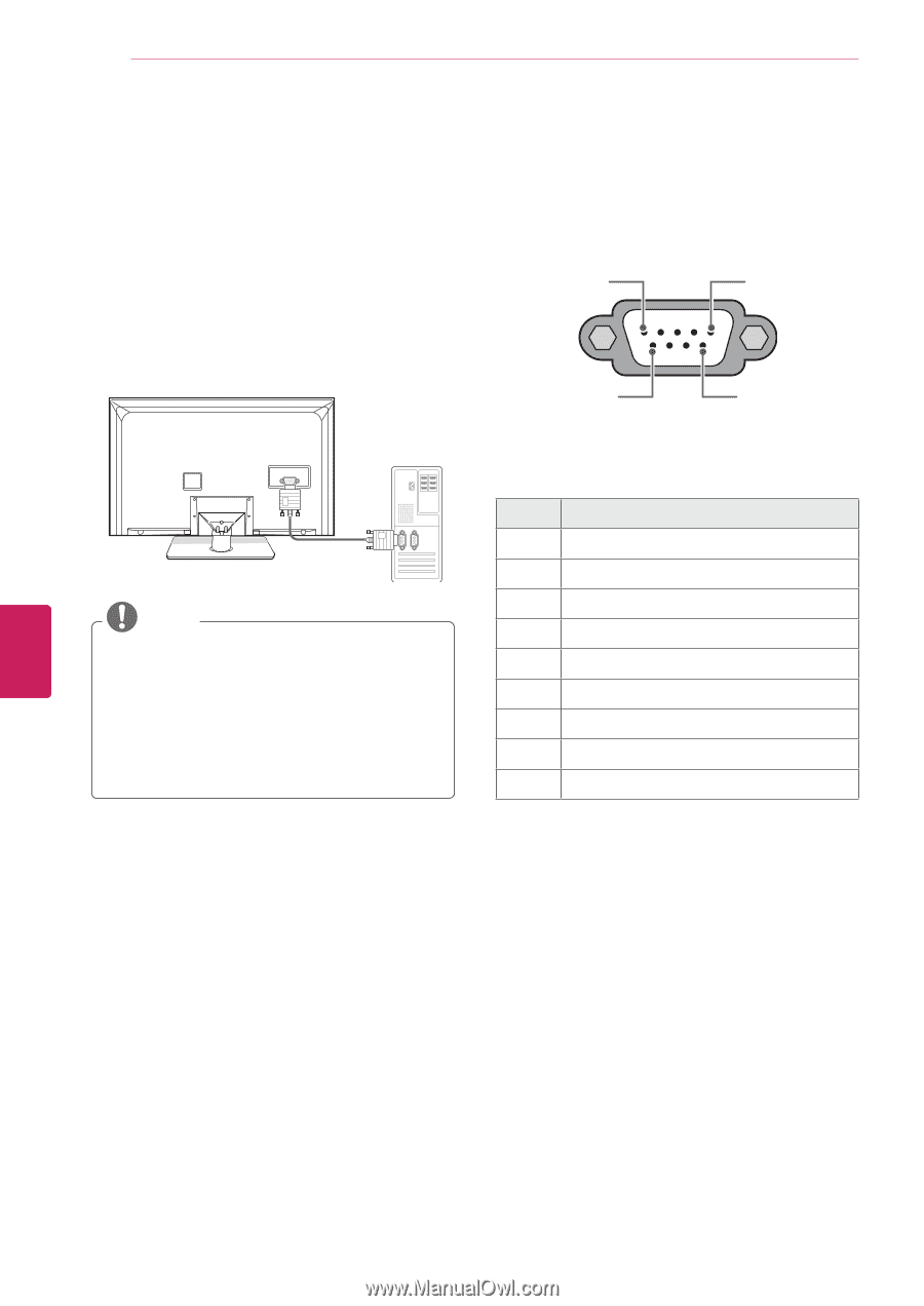
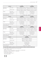
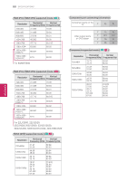
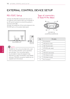
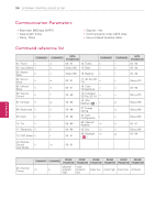
92 EXTERNAL CONTROL DEVICE SETUP EXTERNAL CONTROL DEVICE SETUP RS-232C Setup Connect the RS-232C (serial port) input jack to an external control device (such as a computer or an A/V control system) to control the product's functions externally. Connect the serial port of the control device to the RS-232C jack on the product back panel. RS-232C IN (CONTROL & SERVICE) NOTE yyRS-232C on this unit is intended to be used with third party RS-232C control hardware and software. The instructions below are provided to help with programming software or to test functionality using telenet software. RS-232C connection cables are not supplied with the product. Type of connector; D-Sub 9-Pin Male 1 5 6 9 RS-232C IN (CONTROL & SERVICE) No. Pin name 1 No connection 2 RXD (Receive data) 3 TXD (Transmit data) 4 DTR (DTE side ready) 5 GND 6 DSR (DCE side ready) 7 RTS (Ready to send) 8 CTS (Clear to send) 9 No Connection ENEGNLGISH
-
 1
1 -
2
-
3
-
4
-
5
-
6
-
7
-
8
-
9
-
10
-
11
-
12
-
13
-
14
-
15
-
16
-
17
-
18
-
19
-
20
-
21
-
22
-
23
-
24
-
25
-
26
-
27
-
28
-
29
-
30
-
31
-
32
-
33
-
34
-
35
-
36
-
37
-
38
-
39
-
40
-
41
-
42
-
43
-
44
-
45
-
46
-
47
-
48
-
49
-
50
-
51
-
52
-
53
-
54
-
55
-
56
-
57
-
58
-
59
-
60
-
61
-
62
-
63
-
64
-
65
-
66
-
67
-
68
-
69
-
70
-
71
-
72
-
73
-
74
-
75
-
76
-
77
-
78
-
79
-
80
-
81
-
82
-
83
-
84
-
85
-
86
-
 87
87 -
 88
88 -
 89
89 -
 90
90 -
 91
91 -
 92
92 -
 93
93 -
 94
94 -
 95
95 -
 96
96 -
 97
97 -
98
-
99
-
100
-
101
-
102
-
103
-
104
-
105
-
106
-
107
-
108
-
109
-
110
-
111
-
112
-
113
-
114
-
115
-
116
-
117
-
118
-
119
-
120
-
121
-
122
-
123
-
124
 |
 |