LG DLE5977S Service Manual
LG DLE5977S Manual
 |
View all LG DLE5977S manuals
Add to My Manuals
Save this manual to your list of manuals |
LG DLE5977S manual content summary:
- LG DLE5977S | Service Manual - Page 1
Website:http://www.LGservice.com [For U.S.A] www.lg.ca [For Canada] ELECTRIC & GAS DRYER SERVICE MANUAL CAUTION READ THIS MANUAL CAREFULLY TO DIAGNOSE TROUBLES CORRECTLY BEFORE OFFERING SERVICE. MODEL : DLE5977W/DLG5988W DLE5977B/DLG5988B DLE3777W/DLG3788W - LG DLE5977S | Service Manual - Page 2
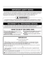
for service, they must be returned to their original position and properly fastened. WHAT TO DO IF YOU SMELL GAS: Do not try to light a match problems are present everywhere. ESD may damage or weaken the electronic control assembly. The new control assembly may appear to work well after repair - LG DLE5977S | Service Manual - Page 3
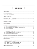
CONTENTS 1. SPECIFICATIONS ...4 2. FEATURES AND BENEFITS ...6 3. INSTALLATION INSTRUCTIONS 6 4. DRYER CYCLE PROCESS ...13 5. COMPONENT TESTING INFORMATION 14 6. MOTOR DIAGRAM AND SCHEMATIC 17 7. CONTROL LAY - OUT ...18 8. WIRING DIAGRAM ...19 9. DIAGNOSTIC TEST ...20 9-1. TEST 1 120VAC ELECTRICAL - LG DLE5977S | Service Manual - Page 4
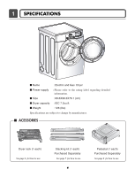
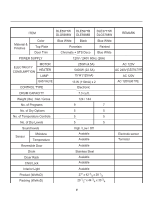
.3X76.1 (cm) I Dryer capacity : IEC 7.3cu.ft. I Weight : 126 (Ibs) Specifications are subject to change by manufacturer. I ACESSORIES Dryer rack (1 each) See page 6 for how to use. Stacking kit (1 each) Purchased Separately See page 7 for how to use. 4 Pedestal (1 each) Purchased Separately - LG DLE5977S | Service Manual - Page 5
CONSUMPTION MOTOR HEATER LAMP 250W (4.5A) 5400W (22.5A) 15 W (125mA) AC 120V AC 240V (ELECTRIC TYPE) AC 120V GAS VALVE CONTROL TYPE 13 W (110mA) x 2 Electronic AC 120V(GAS TYPE) DRUM CAPACITY 7.3 cu.ft. Weight (lbs) : Net / Gross 124 / 144 No. of Programs 9 7 No. of Dry Options - LG DLE5977S | Service Manual - Page 6
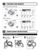
AND BENEFITS DLE5977W/DLG5988W/DLE5977B/DLG5988B DLE3777W/DLG3788W 3 INSTALLATION INSTRUCTIONS Dryer Rack Installation Instructions 1Open the door. Hold the dryer rack with both hands. 2 Put the dryer rack into the drum 3 Make sure that dryer is evenly placed right onto the drum inside and - LG DLE5977S | Service Manual - Page 7
- be careful not to pinch fingers between the washer and dryer. Slide washer slowly backwards to the stopper of kit. 1 Stacking kit Place washer firmly on a stable, even and solid floor as product installation instructions describes in owner's manual. 2 Peel protective paper off the tape from the - LG DLE5977S | Service Manual - Page 8
Pedestal Installation Instructions For washer, dryer, and combo LG 27" 4 Attach the double-faced tape of the bracket to the dryer as shown so the bent parts of the brackets align with the edge and can be attached to the pedestal with screws. NOTE : Attach the lower side first. 1 Remove pedestal, - LG DLE5977S | Service Manual - Page 9
Review the following options to determine the appropriate electrical connection for your home: 4-wire receptacle (NEMA type14-30R) Use the instructions at this section if your home has a 4-wire receptacle (NEMA type 14-30R) and you will be using a UL listed, 120/240 volt minimum, 30 amp, dryer - LG DLE5977S | Service Manual - Page 10
hook together and screw tightly. Option 1: 4-wire connection with a Power supply cord. • lf your local codes or ordinances do not allow the use of a 3 wire connection, or you are installing your dryer in a mobile home, you must use a 4wire connection. 1. Connect neutral wire(white) of power cord - LG DLE5977S | Service Manual - Page 11
do not allow the connection of a frame-grounding conductor to the neutral wire, use the instructions under Section 3: Optional 3-wire connection. Option 3: Optional 3-wire connection. • If your local codes or ordinances do not allow the connection of a frame-grounding conductor to the neutral wire - LG DLE5977S | Service Manual - Page 12
Stainless Steel Flexible Connector - Use only if allowed by local codes (Use Design A.G.A. Certified Connector) 2 1/8" N.P.T. Pipe Plug (for checking inlet gas pressure) 3 Equipment Shut-Off Valve-Installed within 6' (1.8 m) of dryer 4 Black Iron Pipe Shorter than 20' (6.1 m) - Use 3/8" pipe Longer - LG DLE5977S | Service Manual - Page 13
(5min) (47±5°C) 3Hr AIR DRY - - 30min Saturation No heater N/A N/A Load Motor Heater Off Time: 6min On Time: 10sec Temperature Control for each cycle * Sensor dry : "Dry Level" is set by users. ** Manual dry : "Temperature control" is set by users. Default settings can be adjusted by - LG DLE5977S | Service Manual - Page 14
Component 1. Thermal cut off • Check Top Marking : N130 2. Hi limit Thermostat (Auto reset) 3. Outlet Thermostat ( Auto reset) • Check Top Marking : N85 4. Lamp holder Test Procedure Check result Remark Measure resistance of terminal If thermal fuse is open must • Heater case- to terminal be - LG DLE5977S | Service Manual - Page 15
Component 7. Heater 8. Thermistor 9. Motor Test Procedure Measure resistance of the following terminal Terminal : 1 (COM) - 2 Terminal : 1 (COM) - 3 Terminal : 2 - 3 Check result Resistance value : 10Ω Resistance value : 10Ω Resistance value : 20Ω Remark • Electric type Measure resistance of - LG DLE5977S | Service Manual - Page 16
Component 13. Outlet Thermostat (Auto reset) • Check Top Marking : N95 13. Outlet Thermostat (Manual reset) • Check Top Marking : N100 Test Procedure Measure resistance of terminal to terminal Open at 203 ± 7°F (95 ± 5°C) Close at 158 ± 9°F (70 ± 5°C) Check result Resistance value ∞ Continuity < - LG DLE5977S | Service Manual - Page 17
6 MOTOR DIAGRAM AND SCHEMATIC NOTE When checking Component, be sure to turn Power off, then do voltage discharge sufficiently. Contact On / Off by Centrifugal Switch STOP MODE (When Motor does not operate) RUN MODE (Motor operates) Centrifugal switch Centrifugal switch (Pull Drive forward) 17 - LG DLE5977S | Service Manual - Page 18
7 CONTROL LAY - OUT PWB ASSEMBLY DISPLAY LAY-OUT MODEL DISPLAY AS DIAGNOSTIC TEST MODEL DLE5977W/B DLG5988W/B DLE3777W DLG3788W OP 1 X X X X OPTION PART OP 2 OP 3 OP 4 OP 5 X X O X X O O X X X X X X O X X LED OP 6 DISPLAY P/No X 18:FO 6871EC1115A X 19:FO 6871EC1115B X 18 - LG DLE5977S | Service Manual - Page 19
8 WIRING DIAGRAM ELECTRIC DRYER WIRING DIAGRAM GAS DRYER WIRING DIAGRAM 19 - LG DLE5977S | Service Manual - Page 20
runs GAS TYPE : GAS Valve runs (Display the Temperature of Inside drum.) Gas valve See test 7 4 times Control Off During check, Motor & Heater Off + Lamp On + If the door is open. Buzzer beeps seven times During check, Motor on & Heater If the door is closed. Off + Lamp Off 70 ~ 239 Auto - LG DLE5977S | Service Manual - Page 21
When measuring power, be sure to wear insulated gloves, to and avoid an electric shock. Trouble Symptom No power was applied to Controller. (LED, Display off) Measurement Condition With Dryer Power On; Connector linked to Controller. Check the outlet, is the voltage 110V ~ 125V AC? YES NO - LG DLE5977S | Service Manual - Page 22
Test, tE1 and tE2 Error occur. During operation, Heater would not turn off, or remains on. Difference between actual and sensed temperature is significant. Measurement Condition After turning Power off, measure the resistance. Take 6pin Connector from the Controller. Check if resistance is in - LG DLE5977S | Service Manual - Page 23
Control. (Relay check) • Check Controller connector. • Replace Outlet • Thermostat. (Refer to 'Component') • Check Idler Assembly. • Drum Belt cuts off • Drum Belt takes off from • Motor Pulley. • Replace Idler Switch. • Check Motor.(Refer to 'Motor Diagram & Check') • Check if Control Connector - LG DLE5977S | Service Manual - Page 24
Trouble Symptom Degree of dryness does not match with Dry Level. Measurement Condition Turn the Dryer's Power Off, then measure resistance. Take 6pin Connector from the Controller wire) and Pin (ORANGE wire)? YES • Replace Control and Check. Normal Condition Table 2. IMC Ratio and Display Value - LG DLE5977S | Service Manual - Page 25
opening Door, Drum motor and Trouble Symptom Heater run continuously; Door Close is not sensed. (Drum motor will not operate. Display will flash at 0.5 second intervals.) Measurement Condition After turning Dryer Power Off, measure resistance. Measure while Door is closed. Check if resistance is - LG DLE5977S | Service Manual - Page 26
1Ω between terminal TH3 (HI-Limit Thermostat). NO YES • Replace TH3 (HI-Limit Thermostat). Check Motor. Check if the value of measured resistance is below 1Ω between terminal NO and at RUN condition. • Check Motor and replace it. YES Check Controller. Check Harness-linking Connector. 26 - LG DLE5977S | Service Manual - Page 27
electric shock. Trouble Symptom While operating, Heating will not work. Drying time takes longer. Measurement Condition With dryer power on Valve 1 Igniter Valve 2 Power On & Start (Normal Cycle) NO When measuring Valve 1 voltage, More than AC 90V? YES NO • Check thermostat Hi limit Safety - LG DLE5977S | Service Manual - Page 28
. Initially, Natural Gas mode is set. Propane Gas Orifice is on sale as a Service Part to authorized servicers only. STEP 1 : VALVE SETTING Full open "Change screw" STEP NCU Propane Gas 4948EL4002B PCU Kit contents : Orifice (Dia. = 1.613mm, for Propane Gas) : Replace Label : Instruction sheet 28 - LG DLE5977S | Service Manual - Page 29
GAS VALVE FLOW START KEY PUSH "VALVE 1" ON IGNITE ON IGNITE TEMPERATURE ABOUT 370"F YES FRAME DETECT OPEN IGNITE OFF "VALVE 2" ON GAS IGNITION YES DRYING NO NO FRAME DETECT CLOSE "VALVE 2" OFF GAS IGNITION START VALVE 1 IGNITER FRAME DETECT VALVE 2 ON ON CLOSE OFF OFF OPEN ON GAS IGNITION - LG DLE5977S | Service Manual - Page 30
11 DISASSEMBLY INSTRUCTIONS Disassemble and repair the unit only after pulling out power plug from the outlet. 1. Remove 3 screws on the upper plate. 2. Push the top plate back ward. 3. Lift the top plate 30 - LG DLE5977S | Service Manual - Page 31
1. Remove 2 screws on the control panel frame. 2. Disconnect the connectors. 3. Pull the control panel assembly upward and then forward. 4. Remove 9 screws on the PWB(PCB) assembly, display. 5. Remove 4 screws on the PWB(PCB) assembly, main. 6. Disassemble the control panel assembly. 31 - LG DLE5977S | Service Manual - Page 32
1. Disassemble the top plate. 2. Disassemble the control panel assembly. 3. Disassemble the door assembly. 4. Remove 2 screws. 5. Remove 4 screws from the top of cabinet cover. 6. Disconnect the harness of door switch. 32 - LG DLE5977S | Service Manual - Page 33
-1 1. Disassemble the top plate. -1 2. Remove the Cabinet Cover and Tub drum [front]. -2 3. Loosen belt from motor and idler pulleys. 4. Carefully remove Drum out. 1. Disassemble the door. 2. Remove a screw by holding the drum lamp shield in place. 3. Slide the shield up and remove. 4. Remove - LG DLE5977S | Service Manual - Page 34
the botton, left or right side as desired. (Right Side Vent not available on Gas dryer) , , the order of work. DUCT TAPE 2-2. Reconnect the another duct[11 in( blower housing, and attach the duct to the base. ( Duct is a SVC part) DUCT TAPE 3-1. Pre-assemble 4" elbow with 4" duct. Wrap duct tape - LG DLE5977S | Service Manual - Page 35
Disassembly the top plate. 2. Remove the Cabinet Cover and Tub Drum [Front]. 3. Remove the Drum assembly. 4. Remove 2 screws and cover(Air guide). 5. Remove the bolt and washer. 6. Remove the fan. 7. Disconnect the motor clamp and motor. 1. Disassemble the top plate. 2. Remove the Cabinet Cover and - LG DLE5977S | Service Manual - Page 36
3. Remove filter and 2 screws. 4. Remove the air duct. 1. Disassemble the top plate. 2. Remove the Cover Cabinet and Tub Drum [Front]. 3. Remove the Drum assembly and Tub Drum [Rear]. 4. Disconnect Air duct from the Tub Drum [Front]. 5. Remove the roller from the Tub Drum [Front] and Tub Drum [Rear - LG DLE5977S | Service Manual - Page 37
12 EXPLODED VIEW 12-1. Control Panel & Plate Assembly A210 A130 A140 A120 A110 37 - LG DLE5977S | Service Manual - Page 38
12-2. Cabinet & Door Assembly A390 A700 A330 A320 A310 A800 A600 A550 A500 A510 A400 A420 38 A410 A460 - LG DLE5977S | Service Manual - Page 39
12-3-1. Drum & Motor Assembly : Electric Type F200 K400 K120 K140 K100 K130 K250 K310 K330 K320 K340 K222 K221 K620 K210 K250 K550 K560 K610 K240 F130 F110 F120 K530 F140 K640 K600 K510 K520 K650 39 - LG DLE5977S | Service Manual - Page 40
12-3-2. Drum & Motor Assembly : Gas type K120 F200 K400 K100 K130 K222 K221 K210 K140 K250 K330 K320 K340 K250 K550 K560 K310 K620 K610 K240 M160 M171 - LG DLE5977S | Service Manual - Page 41
K550 THERMISTOR ASSEMBLY 6323EL2001B 6323EL2001B K560 THERMOSTAT ASSEMBLY 6931EL3002A 6931EL3002A K530 DUCT ASSEMBLY 5209EL1006A 5209EL1006A K400 TUB,DRUM[BACK] 3044EL0002B 3044EL0002B F200 DUCT ASSEMBLY 5209EL1001C 5209EL1001C K250 ROLLER ASSEMBLY 4581EL3001A 4581EL3001A F110 HEATER - LG DLE5977S | Service Manual - Page 42
of these components, read carefully the safety precautions in this manual. ¡Æ Note : S(Safety Parts), AL(Alternative parts) LG MODEL : TD-V10050E. TD-V10051E, TD-V10055E S AL LOC DESCRIPTION DLG5988W MODEL P/NO DLG5988B DLG3788W QTY A500 CABINET ASSEMBLY 3091EL0003B 3091EL0003D 3091EL0003B - LG DLE5977S | Service Manual - Page 43
- LG DLE5977S | Service Manual - Page 44
Apr. 2004 PRINTED IN KOREA P/No.:3828EL3005A
-
 1
1 -
 2
2 -
 3
3 -
 4
4 -
 5
5 -
 6
6 -
 7
7 -
8
-
9
-
10
-
11
-
12
-
13
-
14
-
15
-
16
-
17
-
18
-
19
-
20
-
21
-
22
-
23
-
24
-
25
-
26
-
27
-
28
-
29
-
30
-
31
-
32
-
33
-
34
-
35
-
36
-
37
-
38
-
39
-
40
-
41
-
42
-
43
-
44
 |
 |

Website:http://www.LGservice.com [For U.S.A]
www.lg.ca [For Canada]
ELECTRIC & GAS DRYER
SERVICE MANUAL
CAUTION
READ THIS MANUAL CAREFULLY TO DIAGNOSE
TROUBLES CORRECTLY BEFORE
OFFERING SERVICE.
MODEL :
DLE5977W/DLG5988W
DLE5977B/DLG5988B
DLE3777W/DLG3788W