LG DLE7177WM Service Manual
LG DLE7177WM Manual
 |
View all LG DLE7177WM manuals
Add to My Manuals
Save this manual to your list of manuals |
LG DLE7177WM manual content summary:
- LG DLE7177WM | Service Manual - Page 1
Website: http://us.lgservice.com Canadian Website: http://lg.ca ELECTRIC & GAS DRYER SERVICE MANUAL CAUTION READ THIS MANUAL CAREFULLY IN ORDER TO PROPERLY DIAGNOSE PROBLEMS AND TO SAFELY PROVIDE QUALITY SERVICE ON THESE DRYERS. MODEL : DLE8377WM/DLG8388WM DLE8377NM/DLG8388NM DLE7177WM/DLG7188WM - LG DLE7177WM | Service Manual - Page 2
JAN. 2006 PRINTED IN KOREA P/No.:3828EL3005D - LG DLE7177WM | Service Manual - Page 3
, straps, clips, nuts, or washers used to complete a path to ground are removed for service, they must be returned to their original position and properly fastened. WHAT TO DO IF YOU SMELL GAS: Do not try to light a match, or cigarette, or turn on any gas or electrical appliance. Do not touch any - LG DLE7177WM | Service Manual - Page 4
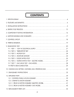
TEST 24 9-4. TEST 4 MOISTURE SENSOR 25 9-5. TEST 5 DOOR SWITCH TEST 26 9-6. TEST 6 HEATER SWITCH TEST - ELECTRIC MODEL 27 9-7. TEST 7 GAS VALVE TEST - GAS MODEL 28 9-8 TEST 8 SEMI-CONDUCTOR 29 10. CHANGE GAS SETTING (NATURAL GAS, PROPANE GAS 30 11. DISASSEMBLY INSTRUCTIONS 32 12. EXPLODED - LG DLE7177WM | Service Manual - Page 5
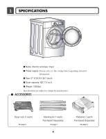
. I Size: 27 X 29.9 X 38.7 (inch) I Dryer capacity: IEC 7.3 cu.ft. I Weight: 126(Ibs) Specifications are subject to change by manufacturer. I ACCESSORIES Dryer rack (1 each) See page 6 Stacking kit (1 each) Purchased Separately See page 7 4 Pedestal (1 each) Purchased Separately See page 8 - LG DLE7177WM | Service Manual - Page 6
ELECTRICITY CONSUMPTION MOTOR HEATER LAMP GAS VALVE CONTROL TYPE DRUM CAPACITY Weight (lbs) - Net/Gross No. of Programs No. of Dry Options No. of Temperature Controls No. of Dry Levels Sound levels Sensor Moisture Temperature Reversible Door Drum Dryer Rack Child Lock Interior Light - LG DLE7177WM | Service Manual - Page 7
SENSOR DRY 0:20 EST. TIME REMAINING OFF MID HIGH 3 INSTALLATION INSTRUCTIONS Dryer Rack Installation Instructions 1Open the door. Hold the dryer rack with both hands. 2 Put the dryer rack into the drum 3 Check and be sure that the front of the rack is properly seated behind the lint filter - LG DLE7177WM | Service Manual - Page 8
careful not to pinch fingers between the washer and dryer. Slide the dryer back against the stop on the side rail. 1 2 Stacking kit Place the washer firmly on a stable, even and solid floor as product installation instructions describe in the owner's manual. Peel the protective paper from the tape - LG DLE7177WM | Service Manual - Page 9
against NthOe bTaEse:aAntdtatchhe tdhreyelro.wer side first. 1 Remove pedestal, installation hardware, and instructions from the shipping carton. 2 Position the dryer on top of the pedestal. , for washer/ combo for dryer 5 Be sure to press the adhesive parts of the brackets firmly to the appliance - LG DLE7177WM | Service Manual - Page 10
Dryer Only Review the following options to determine the appropriate electrical connection for your home: 4-wire receptacle (NEMA type14-30R) Use the instructions under option 1 if your home homehas a 4-wire receptacle (NEMA type 14-30R). 3-wire receptacle (NEMA type10-30R) Use the instructions - LG DLE7177WM | Service Manual - Page 11
wire connection with a Power supply cord. • lf your local codes or ordinances do not allow the use of a 3 wire connection, or you are installing your dryer in a mobile home, you must use a 4wire connection. 1. Connect neutral wire(white) of power cord to center terminal block screw. 2. Connect red - LG DLE7177WM | Service Manual - Page 12
codes or ordinances permit the connection of a frame-grounding conductor to the neutral wire, use these instructions. If your local codes or ordinances do not allow the connection of a frame-grounding conductor to enough to allow the appliance to be moved, if necessary, for service or cleaning.) - LG DLE7177WM | Service Manual - Page 13
Turn on gas and check all pipe connections (internal & external) for gas leaks with a non-corrosive leak detection fluid. 5. For L.P. (Liquefied Petroleum) gas connection, refer to section on Gas (for checking inlet gas pressure) 3 Equipment Shut-Off Valve-Installed within 6' (1.8 m) of dryer 4 - LG DLE7177WM | Service Manual - Page 14
- 20min Saturation (66±5°C) (5min) (47±5°C) 3Hr AIR DRY - - 30min Saturation No heater N/A N/A Load Motor Heater Off Time: 6min On Time: 10sec Temperature Control for each cycle * Sensor dry : "Dry Level" is set by users. ** Manual dry : "Temperature control" is set by users. Default - LG DLE7177WM | Service Manual - Page 15
Outlet Thermostat ( Auto reset) • Check Top Marking: N85 4. Lamp holder Test Procedure Check result Remark Measure resistance of terminal If thermal fuse is open must • Heater case- to terminal be replaced Safety Open at 266 ± 12°F (130 ± 7°C) Resistance value ∞ • Electric type Auto reset - LG DLE7177WM | Service Manual - Page 16
: 10Ω • Heater case Hi limit • Electric type • See Page 13 10. Gas valve valve 1 Measure resistance of the following terminal Valve 1 terminal Valve 2 terminal • Gas type Resistance value: > 1.5 kΩ Resistance value: > 1.5~2.5 kΩ 11. Igniter valve 2 Measure resistance of terminal to terminal - LG DLE7177WM | Service Manual - Page 17
to terminal Open at 203 ± 7°F (95 ± 5°C) Close at 158 ± 9°F (70 ± 5°C) Check result Resistance value ∞ Continuity < 1Ω Remark • Gas type • Gas funnel • Check Top Marking: N95 14. Outlet Thermostat (Manual reset) • Check Top Marking: N100 Measure resistance of terminal to terminal Open at 212 - LG DLE7177WM | Service Manual - Page 18
6 MOTOR DIAGRAM AND SCHEMATIC NOTE When checking Component, be sure to turn Power off, then do voltage discharge sufficiently. Contact On / Off by Centrifugal Switch STOP MODE (When Motor does not operate) RUN MODE (Motor operates) Centrifugal switch Centrifugal switch (Pull Drive forward) 17 - LG DLE7177WM | Service Manual - Page 19
MODEL DISPLAY AS DIAGNOSTIC TEST MODEL DLE8377WM/ DLE8377NM DLG388WM/ DLG8388NM DP 1 X OPTION PART DP 3 X O X OP 5 X X PWB ASSEMBLY LAYOUT LED DISPLAY P/No ELETRIC 6871EL1011A GAS 6871EL1011B MODEL AS DIAGNOSTIC TEST MODEL DLE8377WM/ DLE8377NM DLG388WM/ DLG8388NM "a" RLY200 O X "b"x5 - LG DLE7177WM | Service Manual - Page 20
3 BELT SWITCH NC 123 1 2 3 7 10 MOTOR WHITE DOOR SWITCH OVERLOAD PROTECTOR BLUE ORANGE RED BLUE HEATER 2 1 2 1 MOISTURE THERMISTOR SENSOR RED SAFETY THERMOSTAT OUTER COIL INNER COIL CENTRIFUGAL SWITCH BLOWER WHITE THERMOSTAT RED RED HI - LIMIT THERMOSTAT MOISTURE SENSOR GAS DRYER WIRING - LG DLE7177WM | Service Manual - Page 21
~ 239 Measured Moisture Value. Displays Moisture Sensor Operation: If moisture sensor is contacted with damp cloth. The display number is below 180, in normal condition. See test 3 See test 4 Twice 3 times ELECTRIC TYPE Motor + Heater 1 (2700W) GAS TYPE Motor + Valve ELECTRIC TYPE Motor + Heater - LG DLE7177WM | Service Manual - Page 22
be sure to wear insulated gloves, to and avoid an electric shock. Trouble Symptom No power was applied to Controller. (LED,LCD Display off) Measurement Condition With Dryer Power On; Connector linked to Controller. BK2 or WH2 WH1 BK WH 12 1 Check the outlet, is the voltage 110V ~ 125V AC? YES - LG DLE7177WM | Service Manual - Page 23
electric shock. Trouble Symptom Check the Tab Relays Connection properly. Measurement Condition With Dryer Turn on Heater1. Trans ❈ PCB ASSEMBLY LAYOUT < Table 2 > : Connection of the Tab Relay with Burner (Gas 1 2 Black Wire Connector Housing Check the Matching color Between Harness wire and Tab - LG DLE7177WM | Service Manual - Page 24
Gas) Color Harness PCB Connector Housing Black Blue Wire 1 2 Black Wire Connector Housing Tap relay 1 Remark Check the Matching Relay and Connector Housing (Gas) Items Case Heater1 check the Connection of "2.Status Table of Connection". In case of power failure(-4), please check - LG DLE7177WM | Service Manual - Page 25
with the Ground.) Trouble Symptom During Diagnostic Test, tE1 and tE2 Error occur. During operation, Heater would not turn off, or remains Wire) to Controller. YES • Check if Control and the 6 pin connector are properly connected. • Replace Controller. NO Check if resistance is in the range - LG DLE7177WM | Service Manual - Page 26
Control. (Relay check) • Check Controller connector. • Replace Outlet • Thermostat. (Refer to 'Component') • Check Idler Assembly. • Drum Belt cuts off • Drum Belt takes off from Motor Pulley. • Replace Idler Switch. • Check Motor. (Refer to 'Motor Diagram & Check') • Check if Control Connector - LG DLE7177WM | Service Manual - Page 27
Test 4 Moisture sensor Caution Before measuring resistance, be sure to turn Power off, and do voltage discharge. (When discharging, contact the metal plug of Power cord with earth line.) Trouble Symptom Degree of dryness does not match with Dry Level. Measurement Condition Turn the Dryer's Power - LG DLE7177WM | Service Manual - Page 28
Drum motor and Trouble Symptom Heater run continuously) Door Close is not sensed. (Drum motor will not operate. Display will flash at 0.5 second intervals.) Measurement Condition After turning Dryer Power Off, measure resistance. BK2 WH1 12 1 1 Measure while Door is closed. Check it resistance - LG DLE7177WM | Service Manual - Page 29
6 Heater switch test - Electric Type Caution Before measuring resistance, be sure to turn Power off, and do voltage discharge. (When discharging, contact the metal plug of Power cord with earth line.) Trouble Symptom While operating, Heating will not work. Drying time takes longer. Measurement - LG DLE7177WM | Service Manual - Page 30
to avoid electric shock. Trouble Symptom While operating, Heating will not work. Drying time takes longer. Measurement Condition With dryer power on Valve 1 Igniter Valve 2 Power On & Start (Normal Cycle) NO When measuring Valve 1 voltage, More than DC 90V? YES NO • Check thermostat Hi limit - LG DLE7177WM | Service Manual - Page 31
do voltage discharge. (When discharging, contact the metal plug of Power cord with earth line.) Trouble Symptom Degree of Resistance is not in 300°æ30 Ω Measurement Condition Turn the Dryer's Power Off, then measure resistance. Take 6pin Connector from the Controller. When measuring resistance - LG DLE7177WM | Service Manual - Page 32
improperly can result in an explosion and/or fire. Conversion must be made by a qualified technician. Initially, Natural Gas mode is set. Propane Gas Orifice is on sale as a Service Part to authorized servicers only. STEP 1 : VALVE SETTING Opened Closed Full open Adjustment screw STEP 2 : ORIFICE - LG DLE7177WM | Service Manual - Page 33
PUSH VALVE 1 ON (VALVE 2 OFF) IGNITER ON IGNITER NO TEMPERATURE ABOUT 370°F YES FLAME DETECT OPEN IGNITER OFF VALVE 2 ON GAS IGNITION YES DRYING NO FLAME DETECT CLOSE VALVE 2 OFF GAS IGNITION START VALVE 1 IGNITER FLAME DETECT VALVE 2 ON ON CLOSE OFF OFF OPEN ON GAS IGNITION GAS VALVE - LG DLE7177WM | Service Manual - Page 34
11 DISASSEMBLY INSTRUCTIONS ✽ Disassemble and repair the unit only after pulling out power plug from the outlet. TOP PLATE ! WARNING ! When you disassemble the top plate, be sure to take gloves - LG DLE7177WM | Service Manual - Page 35
CONTROL PANEL ASSEMBLY ! WARNING ! When you disassemble the control panel, be sure to take gloves and careful panel frame's edge. Failure to do so can cause serious injury. 1. Remove 2 screws on the control panel frame. 2. Disconnect the connectors. 3. Pull the control panel assembly upward and - LG DLE7177WM | Service Manual - Page 36
COVER CABINET ! WARNING ! When you disassemble the door switch connector, be sure to take gloves and careful cabinet edge. Failure to do so can cause serious injury. 1. Disassemble the top plate. 2. Disassemble the control panel assembly. 3. Disassemble the door assembly. 4. Remove 2 screws. 5. - LG DLE7177WM | Service Manual - Page 37
plate. 2. Remove Cover Cabinet. 3. Disconnect the door lamp and electrode sensor connector. 4. Remove 4 screws. 5. Disassemble the Tub Drum [Front]. plate. 2. Remove the Cabinet Cover and Tub drum [front]. 3. Loosen belt from motor and idler pulleys. 4. Carefully remove the drum. CHANGING THE DRUM - LG DLE7177WM | Service Manual - Page 38
the botton, left or right side as desired. (Right Side Vent not available on Gas dryer the order of work. DUCT TAPE 2-2. Reconnect the another duct [11 in (28cm)] to the blower housing, and attach the duct to the base. (Duct is a SVC part) DUCT TAPE 3-1. Pre-assemble 4" elbow with 4" duct. Wrap - LG DLE7177WM | Service Manual - Page 39
1. Remove the filter. 2. Remove 3 screws. 3. Remove the Cover Grid. 4. Disconnect the electrode sensor. 1. Disassemble the top plate. 2. Remove the Cabinet Cover and Tub Drum [Front]. 3. Remove the Drum assembly. 4. Remove 2 screws and cover (Air guide). 5. Remove the bolt and washer. 6. Remove the - LG DLE7177WM | Service Manual - Page 40
the Cover Cabinet. 3. Remove the filter and 2 screws. 4. Remove the air duct. 1. Disassemble the top plate. 2. Remove the Cover Cabinet and Tub Drum [Front]. 3. Remove the Drum assembly and Tub Drum [Rear]. 4. Disconnect the Air duct from the Tub Drum [Front]. 5. Remove the roller from the Tub Drum - LG DLE7177WM | Service Manual - Page 41
12 EXPLODED VIEW 12-1. Control Panel & Plate Assembly A211 A210 A130 A140 A120 A110 40 - LG DLE7177WM | Service Manual - Page 42
12-2. Cabinet & Door Assembly A390 A700 A800 A570 A560 A330 A320 A310 A300 A305 A530 A400 A525 A540 A600 A550 A500 A520 A510 A430 A420 41 A450 A410 A460 - LG DLE7177WM | Service Manual - Page 43
12-3-1. Drum & Motor Assembly: Electric Type F200 K400 K120 K140 K100 K130 K222 K221 K210 K350 K240 F130 F110 F120 K250 K251 K310 K330 K320 K340 K230 K250 K620 K360 K610 K550 K560 K251 K570 F140 K540 K510 K520 K530 K640 K651 K650 K600 42 - LG DLE7177WM | Service Manual - Page 44
12-3-2. Drum & Motor Assembly: Gas type K120 K140 K100 F200 K400 K130 K222 K221 K230 K210 K350 K250 K251 K330 K320 K340 K250 K251 K570 K360 K550 M141 M150 M240 M220 M160 M171 M170 M140 M110 M181 M190 M180 M230 M250 43 K530 K640 K651 K650 K600 M210 M171: Propane Gas orifice M170: Natural - LG DLE7177WM | Service Manual - Page 45
in this manual. ¡Æ Note: S(Safety Parts), AL (Alternative parts) LG MODEL: TD ROLLER ASSEMBLY K240 DUCT ASSEMBLY 4581EL3001A 4581EL3001A 5209EL1002A 5209EL1002A K320 COVER, GUIDE 3550EL1006B 3550EL1006B K340 SENSOR K330 GUIDER, FILTER K310 FILTERASSEMBLY, LINT A800 SIDE VENTING KIT 6871EC1120A - LG DLE7177WM | Service Manual - Page 46
manual. ¡Æ Note: S(Safety Parts), AL (Alternative parts) LG ROLLER ASSEMBLY 4581EL3001A 4581EL3001A K240 DUCT ASSEMBLY 5209EL1002A 5209EL1002A K320 COVER,GUIDE 3550EL1006B 3550EL1006B K340 SENSOR 6500EL3001A 6500EL3001A K330 GUIDER, FILTER 4974EL1003B 4974EL1003B K310 FILTERASSEMBLY, LINT
-
 1
1 -
 2
2 -
 3
3 -
 4
4 -
 5
5 -
 6
6 -
 7
7 -
8
-
9
-
10
-
11
-
12
-
13
-
14
-
15
-
16
-
17
-
18
-
19
-
20
-
21
-
22
-
23
-
24
-
25
-
26
-
27
-
28
-
29
-
30
-
31
-
32
-
33
-
34
-
35
-
36
-
37
-
38
-
39
-
40
-
41
-
42
-
43
-
44
-
45
-
46
 |
 |

U.S.A. Website: http://us.lgservice.com
Canadian Website: http://lg.ca
ELECTRIC & GAS DRYER
SERVICE MANUAL
CAUTION
READ THIS MANUAL CAREFULLY IN ORDER TO
PROPERLY DIAGNOSE PROBLEMS AND TO SAFELY
PROVIDE QUALITY SERVICE ON THESE DRYERS.
MODEL : DLE8377WM/DLG8388WM
DLE8377NM/DLG8388NM
DLE7177WM/DLG7188WM