LG DLG0332W Owner's Manual - Page 15
Option 1, Wire Connection with, a Power Supply Cord - front panel
 |
View all LG DLG0332W manuals
Add to My Manuals
Save this manual to your list of manuals |
Page 15 highlights
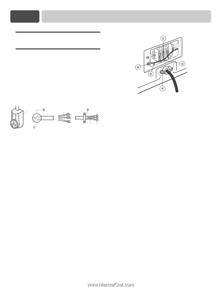
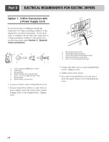
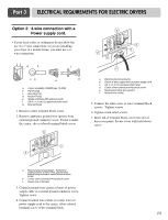
Part 3 ELECTRICAL REQUIREMENTS FOR ELECTRIC DRYERS Option 1: 3-Wire Connection with a Power Supply Cord lf your local codes or ordinances permit the connection of a frame-grounding conductor to the neutral wire, use these instructions. If your local codes or ordinances do not allow the connection of a frame-grounding conductor to the neutral wire, use the instructions under Section 3: Optional 3-wire connection. a d gf a. 3-wire receptacle (NEMA type 10-30R) b. 3-wire plug c. Neutral prong d. Spade terminals with up turned ends e. 3/4 in. (1.9 cm) UL approved strain relief f. Ring terminals g. Neutral (white or center wire) 1. Loosen or remove center terminal block screw. 2. Connect neutral wire (white or center wire) of power supply cord to the center, silver colored terminal screw of the terminal block. Tighten screw. a. External ground connector b. Neutral grounding wire (green) c. Center silver-colored terminal block screw d. Neutral wire (white or center wire) e. 3/4 in. (1.9 cm) UL-listed strain relief 3. Connect the other wires to outer terminal block screws. Tighten screws. 4. Tighten strain relief screws. 5. Insert tab of terminal block cover into slot of dryer rear panel. Secure cover with hold-down screw. 14
-
 1
1 -
2
-
3
-
4
-
5
-
6
-
7
-
8
-
9
-
 10
10 -
 11
11 -
 12
12 -
 13
13 -
 14
14 -
 15
15 -
 16
16 -
 17
17 -
 18
18 -
 19
19 -
 20
20 -
21
-
22
-
23
-
24
-
25
-
26
-
27
-
28
-
29
-
30
-
31
-
32
-
33
-
34
-
35
-
36
-
37
-
38
-
39
-
40
-
41
-
42
-
43
-
44
-
45
-
46
-
47
-
48
-
49
-
50
-
51
-
52
-
53
-
54
-
55
-
56
-
57
-
58
-
59
-
60
 |
 |