LG DLG3788W Owners Manual - Page 9
STEP 3, Connecting, the Exhaust, and Venting, System. - gas dryer
 |
View all LG DLG3788W manuals
Add to My Manuals
Save this manual to your list of manuals |
Page 9 highlights
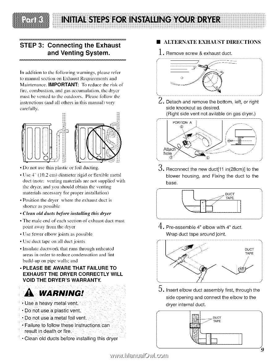
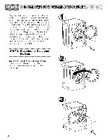
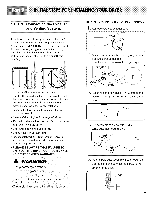
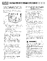
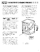
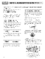
STEP 3: Connecting the Exhaust and Venting System. In addition to the following warnings, please refer to manual section on Exhaust Requirements and Maintenance. IMPORTANT." To reduce the risk of fire, combustion, and gas accumulation, the dryer must be vented to the outdoors. Please follow the instructions (and all others in this manual) very carefully. • Do not use thin plastic or foil ducting. • Use 4" (10.2 cm) diameter rigid or flexible metal duct (note: venting materials are not supplied with the dryer, and you should obtain the venting materials necessary for proper installation) • Position the dryer where the exhaust duct is shorter as possible • Clean old ducts beJbre installing this dryer • The male end of each section of exhaust duct must point away from the dryer • Use fewer elbow joints as possible • Use duct tape on all duct joints • Insulate ductwork that runs through unheated areas in order to reduce condensation and lint build-up on pipe walls; and • PLEASE BE AWARE THAT FAILURE EXHAUST THE DRYER CORRECTLY VOID THE DRYER'S WARRANTY. TO WILL WARNING! • Use a heavy metal vent. • Do not use a plastic vent. • Do not use a metal foil vent. • Failure to follow these instructions can result in death or fire. • Clean old ducts before installing this dryer • ALTERNATE EXHAUST DIRECTIONS 1. Remove screw & exhaust duct. '3 /_,, Detach and remove the bottom, left, or right side knockout as desired. (Right side vent not avitable on gas dryer.) f PORTION A i "_ ® hol_) \ (# J 3, Reconnect the new duct[11 in(28cm)] to the blower housing, and Fixing the duct to the base. 4. Pre-assembte 4" elbow with 4" duct. Wrap duct tape around joint. DUCT TAPE 5. Insert elbow duct assembly first, through the side opening and connect the elbow to the dryer internal duct. J
-
 1
1 -
2
-
3
-
 4
4 -
 5
5 -
 6
6 -
 7
7 -
 8
8 -
 9
9 -
 10
10 -
 11
11 -
 12
12 -
 13
13 -
 14
14 -
15
-
16
-
17
-
18
-
19
-
20
-
21
-
22
-
23
-
24
-
25
-
26
-
27
-
28
-
29
-
30
-
31
-
32
 |
 |