LG HBLG6000R Service Manual
LG HBLG6000R Manual
 |
View all LG HBLG6000R manuals
Add to My Manuals
Save this manual to your list of manuals |
LG HBLG6000R manual content summary:
- LG HBLG6000R | Service Manual - Page 1
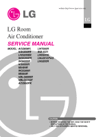
website http://www.lgservice.com LG LG Room Air Conditioner SERVICE MANUAL MODEL: ACQ058PL KG5200ER LW5200ER WG5200ER WG6000R KG6000R M5404R WG5200R M6004R HBLG6000R HBLG5200E ACQ052PK LW7000R WM-5031 LW050CE LWJ0515PAG LW5200R CAUTION • BEFORE SERVICING THE UNIT, READ THE SAFETY PRECAUTIONS - LG HBLG6000R | Service Manual - Page 2
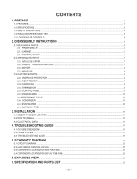
PANEL...9 2.3.6 POWER CORD ...10 2.4 REFRIGERANT CYCLE ...10 2.4.1 CONDENSER ...10 2.4.2 EVAPORATOR ...10 2.4.3 CAPILLARY TUBE ...11 3. INSTALLATION ...13 3.1 SELECT THE BEST LOCATION ...13 3.2 HOW TO INSTALL ...13 3.3 ELECTRICAL DATA ...16 4. TROUBLESHOOTING GUIDE ...16 4.1 OUTSIDE DIMENSIONS ...16 - LG HBLG6000R | Service Manual - Page 3
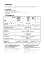
1. PREFACE This service manual provides various service information, including the mechanical and electrical parts, etc. This room air conditioner was manufactured and assembled under a strict quality control system. The refrigerant is charged at the factory. Be sure to read the safety precautions - LG HBLG6000R | Service Manual - Page 4
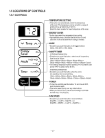
1.5 LOCATIONS OF CONTROLS 1.5.1 CONTROLS Dry Fan Cool TEMPERATURE SETTING • This button can automatically control the temperature of the room. The temperature can be set within a range of 60°F(16°C) to 86°F(30°C) by 1°F(1°C). Select the lower number for lower temperature of the room. ENERGY SAVER - LG HBLG6000R | Service Manual - Page 5
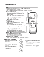
1.5.2 REMOTE CONTROLLER POWER • To turn the Set ON, push the button. To turn the Set OFF, push the button again. • This button takes priority over any other buttons. • When you first turn it on, the Set is on the High cool mode and the temp. at 72°F(22°C). TEMPERATURE SETTING • This button can - LG HBLG6000R | Service Manual - Page 6
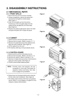
2. DISASSEMBLY INSTRUCTIONS 2.1 MECHANICAL PARTS 2.1.1 FRONT GRILLE 1. Disconnect the unit from source of and air guide. (See Figure 4) 5. Pull the control board toward yourself. NOTE : Controls, wires, and capacitor are now accessible for servicing. Discharge the capacitor before servicing. See - LG HBLG6000R | Service Manual - Page 7
4. Remove the control board. (Refer to Section 2.1.3) 5. Remove the air guide upper. (Refer to Section 2.2.1) 6. Remove 2 screws that secure the base Figure 7) 10. Remove the orfice by pushing the snap area of the air guide blower. (See Figure 8) 11. Remove the clamp springs which are clamped to - LG HBLG6000R | Service Manual - Page 8
fan, fan and shroud. (Refer to Section 2.2.2) 7. Remove the motor. (Refer to Section 2.2.3) 8. Remove 2 screws that secure the air guide to the base pan. (See Figure 11) 9. Push the air guide backward and lift it upward. (See Figure 11) 10. Re-install by referring to the procedures above. Figure 11 - LG HBLG6000R | Service Manual - Page 9
2.3.2 COMPRESSOR 1. Remove the front grille and cabinet. (Refer to Section 2.1.2) 2. Discharge the refrigerant by using a refrigerant recovery system. 3. Remove the overload protector. (Refer to Section 2.3.1) 4. After discharging the unit completely, unbrace the suction and discharge pipes at the - LG HBLG6000R | Service Manual - Page 10
EVAPORATOR 1. Remove the cabinet. (Refer to Section 2.1.2) 2. Discharge the refrigerant by using a refrigerant recovery system. 3. Remove the air guide upper. (Refer to Section 2.2.1) 4. After discharging the refrigerant completely, unbraze the interconnecting tube at the evaporator connections - LG HBLG6000R | Service Manual - Page 11
TUBE 1. Remove the cabinet. (Refer to Section 2.1.2) 2. Discharge the refrigerant by using a refrigerant recovery system. 3. Remove the air guide upper. (Refer to Section 2.2.1) 4. After discharging the refrigerant completely, unbraze the interconnecting tube of the capillary tube. 5. Remove the - LG HBLG6000R | Service Manual - Page 12
equipment, pinch-off tool capable of making a vapor proof seal, leak detector, tubing cutter, hand tools to remove components and service valve. COMPOUND GAUGE MANIFOLD GAUGE B A CONDENSER (HIGH PRESSURE SIDE) COMPRESSOR SEE INSETS BELOW EVAPORATOR (LOW PRESSURE SIDE) CAPILLARY TUBE LO - LG HBLG6000R | Service Manual - Page 13
OUTSIDE AWNING FENCE HEAT RADIATION 30"-60" Figure 21 ABOUT / 1 4 " Over 20" 3.2 HOW TO INSTALL 3.2.1 WINDOW REQUIREMENTS INNER SILL NOTE: All supporting parts should be secured to firm wood, masonry, or metal. 1. This unit is designed for installation in standard dou- ble hung windows - LG HBLG6000R | Service Manual - Page 14
D: 1EA (SEAL STRIP) (Adhesive backed) TYPE E: 1EA (SASH SEAL) (Not adhesive backed) TYPE F: 2EA (GUIDE PANEL) TYPE G: 1EA (SUPPORT BACKET) 3.2.2 BEFORE INSTALLATION 1. Insert the guide panels into the guides of the air conditioner. Fasten the curtains to the unit with screws (TYPE A), as shown - LG HBLG6000R | Service Manual - Page 15
as shown in Figure. 30. Figure 28 CENTER LINE WINDOW FRAME UPPER GUIDE SEAL BOTTOM GUIDE ABOUT 1/4" 5. INSTALL THE SASH SEAL AND SASH LOCK a. Cut the sash A TYPE B SASH SEAL (TYPE E) Figure 30 TYPE B Figure 31 Support Bracket (TYPE G) 1 hang 2 push 3.2.4 HOW TO SECURE THE DRAIN PIPE - LG HBLG6000R | Service Manual - Page 16
support bracket installed through the top and bottom of the guide panels, and save for reinstallation later. Close the guide a CSA certified/UL-listed 3-wire (grounding) extension cord, rated 15A, 125V. 4. TROUBLESHOOTING GUIDE 4.1 OUTSIDE DIMENSIONS (unit: mm [in]) 370 (14 9/16") 42 (1 21/ - LG HBLG6000R | Service Manual - Page 17
system. Reference should be made to Figure 33 to follow the refrigerating cycle and the flow of the refrigerant in the cooling cycle. ROOM AIR CONDITIONER CYCLE OF REFRIGERATION EVAPORATOR COILS COOLED AIR COMPLETE LIQUID BOIL OFF POINT SUCTION LINE COOL LOW PRESSURE VAPOR ROOM AIR - LG HBLG6000R | Service Manual - Page 18
4.3 TROUBLESHOOTING GUIDE In general, possible trouble is classified in two kinds. The one is called Starting Failure which is caused by an electrical defect. The other is Ineffective Air Conditioning caused by a defect in the refrigeration circuit and improper application. Unit is running but - LG HBLG6000R | Service Manual - Page 19
Check of power source. Check of control panel setting. Fails to Start Check of circuit breaker and fuse. Check control panel. Compressor fails only to start. Drop of power voltage. Defect of compressor capacitor. Capacitor check. Replacement. Improper thermistor setting Loose terminal connection - LG HBLG6000R | Service Manual - Page 20
ELECTRIC PARTS TROUBLESHOOTING GUIDE: Possible Trouble 1 • The unit does not operate. NO Is the Trans output power AC 115V? YES Is the Trans output power NO about AC 14V? YES Is - LG HBLG6000R | Service Manual - Page 21
Is the voltage N0.7 of NO IC01M DC 5V? YES • Exchange IC01M. Possible Trouble 3 • The compressor always operate. Is the Unit for 3 minutes NO delay? YES • Check the RY-COMP. • Connect LEAD Wire to RY-COMP again. Possible Trouble 4 • Fan does not operate. Is the voltage NO.1 or 4 NO of - LG HBLG6000R | Service Manual - Page 22
of NO CN-DISP1 all right? YES • Exchange Receiver Ass'y. • Exchange the battery. • Check the P.W.B pattern. • Connect connector to CN-DISP1 exactly. Possible Trouble 6 • It displays abnormally on Display P.W.B Ass'y. NO Is the IC01G all right? YES NO Is the connection of NO CN-DISP1 all - LG HBLG6000R | Service Manual - Page 23
ROOM AIR CONDITIONER VOLTAGE LIMITS NAME PLATE RATING MINIMUM 115V ± 10% 103.5V MAXIMUM 126.5V COMPLAINT Fan motor will not run. Fan motor runs. CAUSE No power Power supply cord Rotary switch Wire disconnected or connection loose Capacitor (Discharge capacitor before testing.) Will not rotate - LG HBLG6000R | Service Manual - Page 24
Blower Loose set screw Worn bearings Compressor will not run, fan motor runs. Voltage Wiring Thermistor Capacitor (discharge capacitor before servicing.) Compressor Overload Compressor cycles on overload. Voltage Overload REMEDY If cracked, out of balance, or partially missing, replace it - LG HBLG6000R | Service Manual - Page 25
cycles on overload CAUSE Fan motor Condenser air flow restriction Insufficient cooling. Excessive noise. Condenser fins (damaged) Capacitor Wiring Refrigeration system Air filter Unit undersized Blower or fan Copper tubing REMEDY If not running, determine the cause. Replace if required - LG HBLG6000R | Service Manual - Page 26
5. SCHEMATIC DIAGRAM 5.1 CIRCUIT DIAGRAM 2 7 3 8 LOCATION NO. 1 2 3 4 5 6 7 8 DESCRIPTION POWER CORD ASSEMBLY FAN MOTOR COMPRESSOR DISPLAY P.W.B ASSEMBLY MAIN P.W.B ASSEMBLY THERMISTOR CAPACITOR OWERLOAD PROTECTOR -26- 1 6 4 5 Q'TY PER SET 1 1 1 1 1 1 1 1 - LG HBLG6000R | Service Manual - Page 27
RY-MED RY-HI R12F 20K 5V CN-WOR C01J 0.1/275V R01J 120 1/2W R02E 20 R01E 1K ZNR01J SVC271D-14A RY-COMP G4A-1A-E-LG FUSE 250V/T2A POWER TRANS 1 7 D02D D05D 2 D03D 4 D04D + C01D D02D~D05D 1000 1N4004 35V 12V IC01D O I 7812 + C02D C03D 0.1 1000 50V 16V IC02D O I 7805 - LG HBLG6000R | Service Manual - Page 28
5.3 COMPONENTS LOCATION (FOR MAIN P.W.B ASM) 5.4 COMPONENTS LOCATION (FOR DISPLAY P.W.B ASM) -28- - LG HBLG6000R | Service Manual - Page 29
6. EXPLODED VIEW 130910 554030 148000 559010 149980 W48602 349480 152302 267110 135312 159900-2 145200 352390-2 359012 W48602 159900-1 354210 135303 135313 264110 W0CZZ 249950 268714 263230 238310 268712 550140 -29- 567502 554160 346811 352390-1 130410 552102 552111 352115 352113 - LG HBLG6000R | Service Manual - Page 30
5211A10062A 5211A10062A 5211A10062B 5211A10062B 5211A10062A 5211A10062B R 352390-1 AIR GUIDE ASSEMBLY 5239A30003A 5239A30003A 5239A30003A 5239A30003A 5239A30003A 5239A30003A R 352390-2 AIR GUIDE ASSEMBLY 5239A10005A 5239A10005A 5239A10005B 5239A10005B 5239A10005A 5239A10005B R 352410 EVAPORATOR - LG HBLG6000R | Service Manual - Page 31
IN 35211A TUBE ASSEMBLY, SUCTION SINGLE 352390-1 AIR GUIDE ASSEMBLY 352390-2 AIR GUIDE ASSEMBLY 352410 EVAPORATOR ASSEMBLY, FIRST 359012 FAN, TURBO 550140 M6004R ACQ058PL ACQ052PK HBLG6000R LW5200ER WM-5031 KG6000R REMARKS LW7000R 3041A10011E 3041A10011F 3041A10011F 3041A10011E 3041A10011E - LG HBLG6000R | Service Manual - Page 32
349480 ORIFICE 352113 TUBE,DISCHARGE 352115 TUBE ASSEMBLY,EVAPORATOR IN 35211A TUBE ASSEMBLY,SUCTION SINGLE 352390-1 AIR GUIDE ASSEMBLY 352390-2 AIR GUIDE ASSEMBLY 354210 EVAPORATOR ASSEMBLY,FIRST 359012 FAN,TURBO 550140 ISOLATOR,COMP 552111 TUBE ASSEMBLY, CAPILLARY 554030 CONDENSER - LG HBLG6000R | Service Manual - Page 33
349480 ORIFICE 35211A TUBE ASSEMBLY, SUCTION SINGLE 352113 TUBE,DISCHARGE 352115 TUBE ASSEMBLY, EVAPORATOR IN 352390-1 AIR GUIDE ASSEMBLY 352390-2 AIR GUIDE ASSEMBLY 352410 EVAPORATOR ASSEMBLY, FIRST 359012 FAN, TURBO 550140 ISOLATOR,COMPRESSOR 552102 TUBE, CAPILLARY BEND 552111 TUBE - LG HBLG6000R | Service Manual - Page 34
P/No.: 3828A20038L January, 2005 Printed in Korea
-
 1
1 -
 2
2 -
 3
3 -
 4
4 -
 5
5 -
 6
6 -
 7
7 -
8
-
9
-
10
-
11
-
12
-
13
-
14
-
15
-
16
-
17
-
18
-
19
-
20
-
21
-
22
-
23
-
24
-
25
-
26
-
27
-
28
-
29
-
30
-
31
-
32
-
33
-
34
 |
 |
LG
Room
Air Conditioner
SERVICE MANUAL
LG
MODEL: ACQ058PL
LW7000R
KG5200ER
WM-5031
LW5200ER
LW050CE
WG5200ER
LWJ0515PAG
WG6000R
LW5200R
KG6000R
M5404R
WG5200R
M6004R
HBLG6000R
HBLG5200E
ACQ052PK
CAUTION
website http://www.lgservice.com
• BEFORE SERVICING THE UNIT, READ THE SAFETY
PRECAUTIONS IN THIS MANUAL.
• ONLY FOR AUTHORIZED SERVICE PERSONNEL.