LG L1717SBN Service Manual
LG L1717SBN - LG - 17" LCD Monitor Manual
 |
View all LG L1717SBN manuals
Add to My Manuals
Save this manual to your list of manuals |
LG L1717SBN manual content summary:
- LG L1717SBN | Service Manual - Page 1
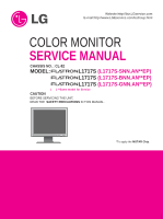
Website:http://biz.LGservice.com E-mail:http://www.LGEservice.com/techsup.html COLOR MONITOR SERVICE MANUAL CHASSIS NO. : CL-82 MODEL: L1717S (L1717S-SNN.AN**EP) L1717S (L1717S-BNN.AN**EP) L1717S (L1717S-GNN.AN**EP) ( ) **Same model for Service CAUTION BEFORE SERVICING THE UNIT, READ THE - LG L1717SBN | Service Manual - Page 2
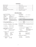
SERVICE OSD 13 TROUBLESHOOTING GUIDE 14 WIRING DIAGRAM 18 EXPLODED VIEW 19 REPLACEMENT PARTS LIST 21 SCHEMATIC DIAGRAM 23 SPECIFICATIONS 1. LCD CHARACTERISTICS Type : TFT Color LCD Typ) Bottom : -50° min., -65°(Typ) 4. Max. Resolution D-sub Analog : 1280 x 1024@75Hz 5. POWER SUPPLY 5-1. - LG L1717SBN | Service Manual - Page 3
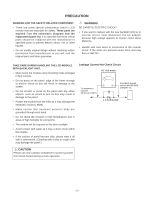
There are some special components used in LCD monitor that are important for safety. These parts or inverter circuit, must disconnect the AC adapter because high voltage appears at inverter circuit about 650Vrms. • Handle with care wires or connectors of the inverter during service operation. -3- - LG L1717SBN | Service Manual - Page 4
with high voltage. 4. Do not spray chemicals on or near this receiver or any of its assemblies. 5. Unless specified otherwise in this service manual, clean electrical contacts only by applying the following mixture to the contacts with a pipe cleaner, cottontipped stick or comparable non-abrasive - LG L1717SBN | Service Manual - Page 5
General Soldering Guidelines 1. Use a grounded-tip, low-wattage soldering iron and appropriate tip size and shape that will maintain tip temperature within the range or 500。F to 600。F. 2. Use an appropriate gauge of RMA resin-core solder composed of 60 parts tin/40 parts lead. 3. Keep the soldering - LG L1717SBN | Service Manual - Page 6
Circuit Board Foil Repair Excessive heat applied to the copper foil of any printed circuit board will weaken the adhesive that bonds the foil to the circuit board causing the foil to separate from or "lift-off" the board. The following guidelines and procedures should be followed whenever this - LG L1717SBN | Service Manual - Page 7
60 54 35 48 33 120 16 88 23 160 21 224 39 160 29 176 28 144 39 200 31 248 38 248 38 Resolution 640 x 350 720 X 400 640 x 480 640 x 480 800 x 600 800 x 600 832 x 624 1024 x 768 1024 x 768 1152 x 870 1152 x 900 1280 x 1024 1280 - LG L1717SBN | Service Manual - Page 8
DISASSEMBLY # 1 # 2 Remove the screws. # 3 1. Pull the front cover upward. 2. Then, let the all latches are separated. 3. Put the front face down. # 4 Disassemble Control PCB. # 5 Disassemble back cover. # 6 Remove the screws. # 7 Pull out the cable. Pull out the link cable while pushing up - LG L1717SBN | Service Manual - Page 9
BLOCK DIAGRAM -9- 3.3V LCD Module 5V 3.3V Reg. 78D33 5V 3.3V Reg. 78D33 3.3V1 R,G,B differential TSU16AL & TR(KTA 1273) LVDS (Low Voltage Differential Signaling) 3.3V 3.3V1 AC I nput 12V - LG L1717SBN | Service Manual - Page 10
the video signal converted analog to digital, interpolates input to 1280 X 1024 resolution signal and outputs 8-bit R, G, B signal to transmitter. 2. Power which is provided 5V in Power board. 12V is provided for inverter, 12V is provided for LCD panel and 5V for micom. Also, 5V is converted 3.3V - LG L1717SBN | Service Manual - Page 11
function is to make a pulse width modulation control and to provide the driver signal to power switch, to adjust the duty cycle during different AC achive the dc output stablize, and also the over power protection is also monitor by this part. 5. Photo-Coupler isolation. This part function is to - LG L1717SBN | Service Manual - Page 12
ADJUSTMENT Windows EDID V1.0 User Manual Operating System: MS Windows 98, 2000, XP Port Setup: Windows 98 => Don't need setup Windows 2000, XP => Need to Port Setup. This program is available to LCD Monitor only. 1. Port Setup a) Copy "UserPort.sys" file to "c:\WINNT\system32\drivers" folder b) Run - LG L1717SBN | Service Manual - Page 13
Gain : Allows you to set the R/G/B-Gain value manually.(Analog Only) i) MODULE : To select applied module. Video Signal Generator Control Line IBM Compatible PC 15 10 5 PARALLEL PORT Not used RS232C PARALLEL OFF ON 5V C F VGS A MONITOR B V-SYNC ST POWER Power inlet (required) 220 - LG L1717SBN | Service Manual - Page 14
TROUBLESHOOTING GUIDE 1. NO POWER NO POWER (POWER INDICATOR OFF) CHECK J705 NO VOLTAGE PIN5, PIN6 (5V)? YES CHECK NO U501 PIN 8 VOLTAGE (5V) ? YES CHECK KEY CONTROL - LG L1717SBN | Service Manual - Page 15
CONTACTING SCOPE PROBE TO CAUTION LABEL. NO (CONTACT PROBE TO CAUTION LABEL. CAN YOU SEE PULSE AT YOUR SCOPE? YES REPLACE CCFL LAMP IN THE LCD MODULE CHECK POWER BOARD, AND FIND OUT A SHORT POINT AS OPENING EACH POWER LINE CHECK MICOM INV ON/OFF PORT. 1. CONFIRM BRIGHTNESS OSD CONTRL STATE - LG L1717SBN | Service Manual - Page 16
, 90 3.3V? YES U201 1 PIN96, 97 NO OSCILLATE AS 12MHZ? YES CHECK U801 (17", 19") CHECK U803 (15") 1. CHECK PIN122, 123 SOLDERING CONDITION 2. CHECK X501 3. TROUBLE IN U201 U501 PIN43 IS 48KHz H-SYNC? 2 PIN44 IS 60Hz V-SYNC? NO IS PULSE APPEARED AT SIGNAL PINS? AT MODE 12? YES - LG L1717SBN | Service Manual - Page 17
4. TROUBLE IN DPM TROUBLE IN DPM CHECK 3 R216, R217 R778, R781 YES CHECK U501 PIN 43.44 SYNC PULSE ? YES TROUBLE IN U501 CHECK PC NO PC IS NOT GOING INTO DPM OFF MODE NO CHECK H/V SYNC LINE Waveforms 3 R216, R778 H-Sync 3 R217, R781 V-Sync - 17 - - LG L1717SBN | Service Manual - Page 18
WIRING DIAGRAM Connector Ass'y P/N: 6631T11012W or 6631T11020W Connector Ass'y P/N: 6631T20020Q POWER MAIN CONTROL Connector Ass'y P/N: 6631T20022G - 18 - - LG L1717SBN | Service Manual - Page 19
- 19 - 010 110 EXPLODED VIEW 020 060 070 080 030 090 100 050 040 - LG L1717SBN | Service Manual - Page 20
/KUMI,PB FREE,EGI,OKI S D-IC,SXGA,LVDS or 6304FLP275A LCD(LIQUID CRYSTAL DISPLAY), LM170E01-TLA3 LG PHILPS TFT COLOR P5,645CH,250NITS,8MS,LPL NJ/KUMI,PB FREE,EGI,MAGNA S D-IC,EGI,SXGA 030 3809TKL123D BACK COVER ASSEMBLY, L1717S L125 HF350 BK - DI LOCAL-For Europe,Austrailia,U.K 3809TKL123B BACK - LG L1717SBN | Service Manual - Page 21
REPLACEMENT PARTS LIST CAUTION: BEFORE REPLACING ANY OF THESE COMPONENTS, READ CAREFULLY THE SAFETY PRECAUTIONS IN THIS MANUAL. * NOTE : S SAFETY Mark AL ALTERNATIVE PARTS *S *AL LOC. NO. PART NO. MAIN BOARD CAPACITORS DATE: 2005. 06. 02. DESCRIPTION / SPECIFICATION C204 C205 C206 C207 C211 - LG L1717SBN | Service Manual - Page 22
*S *AL LOC. NO. PART NO. DATE: 2005. 06. 02. DESCRIPTION / SPECIFICATION *S *AL LOC. NO. PART NO. DATE: 2005. 06. 02. DESCRIPTION / SPECIFICATION R522 R523 R530 R534 R535 R537 R543 R544 R545 R547 R548 R549 R555 R557 R560 R701 R702 R703 R704 R706 R708 R709 R712 R716 R717 R720 R722 R723 R724 R726 - LG L1717SBN | Service Manual - Page 23
SCHEMATIC DIAGRAM 1. TSU56AL / TSU16AL - 23 - 3 Waveforms 1 U201-#96, 97 1 3 R216, R778 H-Sync 3 R217, R781 V-Sync - LG L1717SBN | Service Manual - Page 24
2 2. MICOM - 24 - Waveforms 2 U501-#43 H-SYNC 2 U501-#44 V-SYNC - LG L1717SBN | Service Manual - Page 25
3.POWER - 25 - - LG L1717SBN | Service Manual - Page 26
3 4. CONNECTOR & JACKS - 26 - Waveforms 3 R216, R778 H-Sync 3 R217, R781 V-Sync - LG L1717SBN | Service Manual - Page 27
P/NO : 38289S0001Z Jun. 2005 Printed in Korea
-
 1
1 -
 2
2 -
 3
3 -
 4
4 -
 5
5 -
 6
6 -
 7
7 -
8
-
9
-
10
-
11
-
12
-
13
-
14
-
15
-
16
-
17
-
18
-
19
-
20
-
21
-
22
-
23
-
24
-
25
-
26
-
27
 |
 |
-
+
COLOR MONITOR
SERVICE MANUAL
Website:http://biz.LGservice.com
CAUTION
BEFORE SERVICING THE UNIT,
READ THE
SAFETY PRECAUTIONS
IN THIS MANUAL.
CHASSIS NO. : CL-82
MODEL:
L1717S
(L1717S-SNN.AN**EP)
L1717S
(L1717S-BNN.AN**EP)
L1717S
(L1717S-GNN.AN**EP)
*To apply the
MSTAR Chip
.
(
) **Same model for Service