LG RD-JT40 Service Manual
LG RD-JT40 Manual
 |
View all LG RD-JT40 manuals
Add to My Manuals
Save this manual to your list of manuals |
LG RD-JT40 manual content summary:
- LG RD-JT40 | Service Manual - Page 1
LG RD-JT40/41 Service Manual RD-JT40/RD-JT41 SERVICE MANUAL C a u tio n Be sure to read this m anual before servicing. To assure safety from fire, electric shock, injury, harm ful radiation and m aterials, various m easures are provided in this Acer DLP projector. Be sure to read cautionary item s - LG RD-JT40 | Service Manual - Page 2
LG RD-JT40/41 Service Manual 1. SPECIFICATIONS Projector Specifications Technical Specifications Note: All specifications are subject to change without notice. General Product name Model name Personal Projector RD-JT40 1024*768XGA RD-JT41 800*600SVGA Optical Display system 1-CHIP DMD Lens F/ - LG RD-JT40 | Service Manual - Page 3
LG RD-JT40/41 Service Manual Service Information Accessories (included in the Standard Package) Description of parts Part No. Power cord (EU) Power cord (US in the Standard Package) Description of parts Part No. Mac adapter (switchable) 20.20118.A15 Spare lamp module 60.J3416.CB1 3 - LG RD-JT40 | Service Manual - Page 4
LG RD-JT40/41 Service Manual 2. Spare Parts List Item No:99.J3477.L11 Projector LG RD-JT40 spare parts list Parts ASSY REAR CVR MODULE DX660/LG ASSY CAP LENS TRANS. DX660 ASSY UPPER CASE P896 DX660/LG PCBA KEYPAD BD DX660 ASSY LAMP MODULE U DX660 ASSY REMOTE+CABLE LG DXS660 CORD H05VV-F 13A250V - LG RD-JT40 | Service Manual - Page 5
LG RD-JT40/41 Service Manual Parts No 55.J3405.001 55.J3408.001 60.J3419.001 55 P896 DS660/LG ASSY LAMP MODULE U DX660 ASSY DOOR LAMP P838 DX660/LG ASSY MANU+WARRANTY LG ASSY REMOTE+CABLE LG DXS660 REMOTE CONTROLLER DXS660 LG SOFT CASE DXS660 LG 3. Shipping Contents The Projector is shipped with - LG RD-JT40 | Service Manual - Page 6
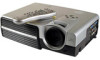
LG RD-JT40/41 Service Manual Optional Accessories 1. Macintosh adapter 2. 210W Lamp module 4. Projector Description Projector 6 - LG RD-JT40 | Service Manual - Page 7
LG RD-JT40/41 Service Manual External Control Panel 7 - LG RD-JT40 | Service Manual - Page 8
LG RD-JT40/41 Service Manual Adjuster 8 - LG RD-JT40 | Service Manual - Page 9
LG RD-JT40/41 Service Manual The projector is equipped with 2 quick-release adjuster feet. Push the buttons to adjust its tilt angle. 1. Lift the projector up and press the adjuster button to release the adjuster. 2. The adjuster will drop into position and be locked. Projector Features The - LG RD-JT40 | Service Manual - Page 10
LG RD-JT40/41 Service Manual The remote control sensors are located in the front/ back of the projector. The distance between the sensor and the remote control should not exceed 6 meters. Installing or Replacing Batteries 10 - LG RD-JT40 | Service Manual - Page 11
LG RD-JT40/41 Service Manual Caution Avoid excessive heat and humidity. There may be danger of an explosion if batteries are incorrectly replaced. Replace only with the same or equivalent type recommended by the manufacturer. Dispose of used batteries according to the manufacturer’s instructions. 11 - LG RD-JT40 | Service Manual - Page 12
LG RD-JT40/41 Service Manual 6. INSTALLATION Screen Size Place the projector at the required distance from the screen YPBPR connector. Use a HDTV cable that came with your projector to display HDTV images. The following standards are supported in the HDTV function: • 480i • 480p • 720p - LG RD-JT40 | Service Manual - Page 13
LG RD-JT40/41 Service Manual Connecting to Various Equipment It only takes a few seconds to connect your projector to your desktop or notebook computer, VCR, or other systems. However, a Mac adapter (an optional accessory) is needed for connection to Macintosh computers. 13 - LG RD-JT40 | Service Manual - Page 14
LG RD-JT40/41 Service Manual 7. OPERATION Start Up 1. Plug the power cord into a wall socket. 2. Turn on the main power switch. 3. Press is turned on (When the power is turned off, there is a 60-second cooling period before the projector can be re-started.) 4. Switch on all connected equipment. 14 - LG RD-JT40 | Service Manual - Page 15
LG RD-JT40/41 Service Manual Digital Keystone Correction Keystoning refers to the situation where the projected image is noticeably wider at either the top or bottom. To correct this, press KEYSTONE +/- (hot key) on the control panel of the projector or on the remote control, and then adjust the - LG RD-JT40 | Service Manual - Page 16
LG RD-JT40/41 Service Manual Source Selection When several input sources are available, press the SOURCE key to make a selection from the control panel of the projector or the remote control. Menu System Press Menu for the main menu, and then press or to select a sub-menu. Press Menu again to select - LG RD-JT40 | Service Manual - Page 17
LG RD-JT40/41 Service Manual 1. Display Menu 17 - LG RD-JT40 | Service Manual - Page 18
LG RD-JT40/41 Service Manual 2. Image Menu 18 - LG RD-JT40 | Service Manual - Page 19
LG RD-JT40/41 Service Manual 3. Source Menu 19 - LG RD-JT40 | Service Manual - Page 20
LG RD-JT40/41 Service Manual 4. Control Menu FUNCTION DESCRIPTION Language sets the language for the OSD before the projector is shut off when Blank is activated. Auto off Sets the length of time before the system is shut off when no input is detected. User logo Enables the user to define - LG RD-JT40 | Service Manual - Page 21
LG RD-JT40/41 Service Manual 5. PIP Menu These functions are available only when the input mode is PC and the PIP source is Video or S-Video 21 - LG RD-JT40 | Service Manual - Page 22
LG RD-JT40/41 Service Manual 8. Shutdown 1. Press POWER and a warning message will appear. POWER again. To turn off the projector, press 2. cooling process. If the projector is not properly shut down, to protect the lamp, the system will detect this and cool the lamp for two minutes automatically - LG RD-JT40 | Service Manual - Page 23
RD-JT40/41 Service Manual 9. MAINTENANCE Lamp Information Use and Replacement of the Lamp When the lamp Indicator lights up red or a message appears suggesting the time of lamp replacement, please install a new lamp or consult your dealer. An old lamp could cause a malfunction in the projector - LG RD-JT40 | Service Manual - Page 24
LG RD-JT40/41 Service Manual 10. Lamp Replacement Caution To reduce the risk of electrical shock, always turn off the projector and disconnect the power cord before changing the lamp 24 - LG RD-JT40 | Service Manual - Page 25
LG RD-JT40/41 Service Manual Caution To reduce the risk of severe burns, allow the projector to cool for at least 45 minutes before replacing the lamp. The reduce the risk of injuries to fingers and damage to internal components, use caution when removing lamp glass that has shattered into sharp - LG RD-JT40 | Service Manual - Page 26
LG RD-JT40/41 Service Manual 11. TROUBLE SHOOTING Common Problems & Solutions PROBLEMS NO POWER NO LAMP WARNING – CHANGE LAMP AND RESET LAMP TIMER! OUT OF LAMP USAGE TIME. CHANGE THE LAMP! OUT OF LAMP USAGE TIME. YOU HAVE TO CHANGE THE LAMP! Description Projector is searching for input. Projector - LG RD-JT40 | Service Manual - Page 27
LG RD-JT40/41 Service Manual 1. Final Assembly Trouble Shooting Guide S y s te m T ro u b le S h o o tin g F lo w C h a r B a c k -L IG H T O K ? Yes Power O N O K? (LA M P O N ?) Yes N o S ig n a l? No A u to P o w e r O ff? No V id e o N G ? No A u d io N G ? No IR R e m o te C o n tro l NG ? No - LG RD-JT40 | Service Manual - Page 28
LG RD-JT40/41 Service Manual 2. Engine Assembly Trouble Shooting Guide A Image NG? (Blank) No Image NG? (Screen flashing) No Image NG? (Screen dimmish) No Image NG? (Freezing) No Image NG? (Missing column bar) No Image - LG RD-JT40 | Service Manual - Page 29
LG RD-JT40/41 Service Manual le n s EE Perform ance OK O ptical Perform ance NG NG S ys te m Trouble sh o o tin g G uide B rightness No Uniform ity No C o n tra t/G ain setup Yes 2.chk D M D baffle 3.chang e projection len s 1.Reset Factory m o de, chk C W dela y Yes 2.change CW 3.chang e - LG RD-JT40 | Service Manual - Page 30
LG RD-JT40/41 Service Manual 3. Main Board Trouble Shooting Guide S yste m n o w o rk No N o d a ta s ig n a l o u tp u t to D M D B D No T h e im a g e d is p la y " N o S ig n a l" w h e n th e in p u t is P C No T h e g h o s t Im a g e d is p la y o u tp u t o f V id e o in p u t No C o u ld n - LG RD-JT40 | Service Manual - Page 31
LG RD-JT40/41 Service Manual 4. Power Supply Trouble Shooting Guide B + B- INPUT 380VDC LINE 0VACOR 220VAC NO YES CHECK SPS B/D. WHETHER POOR SOLDER B + B54VDC YES CHECK PFC B/D. WHETHER POOR SOLDER NO B + B- YES F65 YES Q65 DAMAGE - LG RD-JT40 | Service Manual - Page 32
LG RD-JT40/41 Service Manual 5. Translation Board Trouble Shooting Guide D S 6 6 0 T r a n s la t io n B o a r d T r o u b le S h o o tin g G u id e VCCCPU O K PO W ER O NA f u n c t io n O K ? Y es V C C ,1 2 V f u n c t io n O K ? Y es A b n o rm a l f u n c t io n O K? Y es L A M P E N -S f u n - LG RD-JT40 | Service Manual - Page 33
LG RD-JT40/41 Service Manual 6. DMD Board Trouble Shooting Guide problems with getting LAMPLIT appear. 3.5 seconds after LAMPLIT, DMD should become active (unpark) and display an image. Verify reset (HRESETZ, pin 1) from FPGA to microcontroller only goes low once during the lamp TI electronics between - LG RD-JT40 | Service Manual - Page 34
LG RD-JT40/41 Service Manual 12. Timing Chart 34 - LG RD-JT40 | Service Manual - Page 35
LG RD-JT40/41 Service Manual DMD Image Specification 1. SCOPE This document specifies the image quality requirements applicable to the DLPTM XGA Component Set. The Component Set provides the DLPTM XGA Projector with digital imaging functionality based on Digital Micromirror Device (DMD) technology. - LG RD-JT40 | Service Manual - Page 36
LG RD-JT40/41 Service Manual parallel lines outside of the Sea of Mirrors (SOM). 2.9.2 Exposed Metal 2 under the following projected image test conditions: a. Projector degamma shall be linear. b. Projector error diffusion shall be “off” c. Projector brightness and contrast settings shall be set to - LG RD-JT40 | Service Manual - Page 37
LG RD-JT40/41 Service Manual TABLE 1. Image Quality Specification SEQ # TEST 1 Major Dark Blemish SCREEN Two be the projected image tests referenced in Table 1. 5. Any other image quality issue not specifically defined in this document shall be acceptable. 6. Black screens shall not be used as - LG RD-JT40 | Service Manual - Page 38
LG RD-JT40/41 Service Manual 14. Electrical Interface Character Interface Definition 15 pin definition of the mini D-sub male for DDC1/2B protocol 5 6 0 5 Pin Definition 1 Red video 5 Return +5 Volt Supply 9 ( - LG RD-JT40 | Service Manual - Page 39
LG RD-JT40/41 Service Manual Control Port 87 6 54 3 21 Pin Description Pin 1 Reserved 2 3 TX 4 5 Reserved 6 7 RX 8 Description Reserved Reserved Reserved GND 39 - LG RD-JT40 | Service Manual - Page 40
LG RD-JT40/41 Service Manual contrast should be measured only 5 minute or more after lamp is on. 3. UUT should be placed at a distance ranges from 1.5 to 5 meter. 4. Applied timing should be 1024*768 @65Hz (XGA); 800*600@60Hz (SVGA) Before test, be sure the following configurations are - LG RD-JT40 | Service Manual - Page 41
LG RD-JT40/41 Service Manual Channel S-Video YcbCr YPbPr Prime Mode * * * Timing Pattern Item Criteria NTSC PT2 Gray 0-100% (H: 15.73KHz, Master Pattern H&V Res. 1 Line 29.96Hz, I) Color Hue, Sat - LG RD-JT40 | Service Manual - Page 42
LG RD-JT40/41 Service Manual PT863 Text Movie 720p PT2 (H: 45.00KHz, Master Pattern 60Hz, p) 1080I PT2 (H: 33.75Khz, Master Pattern 30Hz, I) (B) PC EE Check: EM Character Video Essential Gray H&V - LG RD-JT40 | Service Manual - Page 43
LG RD-JT40/41 Service Manual (31.469KHz, Color 59.94Hz) Smear Linearity Jitter, Swing, Snack, Ring, Cross-talk 640*400@85 PT2 Gray Hz Master Pattern H&V Res. (43.269KHz, Color - LG RD-JT40 | Service Manual - Page 44
LG RD-JT40/41 Service Manual (C) Optical Check Equipment: Chroma 2250, CL-100 Aspect Ratio: 4:3 User OSD setting: (PC), 30 gray Final Check Step Screen Check Items 1.Brightness 100% W Pattern ANSI Lumens Uniformity 2.Contrast Ratio Checker Board ANSI C/R R Pattern G Pattern - LG RD-JT40 | Service Manual - Page 45
LG RD-JT40/41 Service Manual 16. PACKING DESCRIPTION CTN LBL PRINTING: 45 - LG RD-JT40 | Service Manual - Page 46
LG RD-JT40/41 Service Manual 46 - LG RD-JT40 | Service Manual - Page 47
LG RD-JT40/41 Service Manual 17. APPEARANCE DESCRIPTION 47 - LG RD-JT40 | Service Manual - Page 48
LG RD-JT40/41 Service Manual SPEC LBL PRINTING LAMP LBL PRINTING 48 - LG RD-JT40 | Service Manual - Page 49
LG RD-JT40/41 Service Manual 18. Dimensions 49 - LG RD-JT40 | Service Manual - Page 50
.J3877.001 DMD CHIP BD Size A3 Document Number 304-C01 48.J3802.S01 FAB:S01 A Rev 0 Date: Monday, March 25, 2002 Sheet Prepared By Reviewed By 1 of 4 Approved By ANGEL HU BILL WJ CHANG T.S.WU 4 3 2 1 - LG RD-JT40 | Service Manual - Page 51
1 2 3 4 T.S.WU BILL WJ CHANG ANGEL HU Approved By Reviewed By Prepared By 4 of 2 Sheet Date: Monday, March 25, 2002 A Rev 0 FAB:S01 48.J3802.S01 Document Number 304-C01 Size A3 99.J3877.001 - LG RD-JT40 | Service Manual - Page 52
.J3877.001 DMD CHIP BD Size A3 Document Number 304-C01 48.J3802.S01 FAB:S01 A Rev 0 Date: Monday, March 25, 2002 Sheet Prepared By Reviewed By 3 of 4 Approved By ANGEL HU BILL WJ CHANG T.S.WU 2 1 - LG RD-JT40 | Service Manual - Page 53
.J3877.001 DMD CHIP BD Size A3 Document Number 304-C01 48.J3802.S01 A Rev FAB:S01 0 Date: Monday, March 25, 2002 Sheet Prepared By Reviewed By 4 of 4 Approved By ANGEL HU BILL WJ CHANG T.S.WU 2 1 - LG RD-JT40 | Service Manual - Page 54
- LG RD-JT40 | Service Manual - Page 55
- LG RD-JT40 | Service Manual - Page 56
- LG RD-JT40 | Service Manual - Page 57
.001 DX660 KEYPAD BD SCHEMAICS Size A3 Document Number 304-C01 48.J3403.S01 FAB:S01 A Rev 0 Date: Saturday, March 02, 2002 Sheet Prepared By Reviewed By 1 of 2 Approved By ANGEL HU BILL WJ CHANG H.C.TSOU 2 1 - LG RD-JT40 | Service Manual - Page 58
Title DX660 KEYPAD BD SCHEMAICS A A Size Document Number Rev A3 304-C01 48.J3403.S01 FAB:S01 0 Date: Saturday, March 02, 2002 Sheet Prepared By Reviewed By 2 of 2 Approved By ANGEL HU BILL WJ CHANG H.C.TSOU 5 4 3 2 1 - LG RD-JT40 | Service Manual - Page 59
RESET WATCHDOG ROMOEn ROMWEn VPPEN EEP_WP A[19:1] D[0:15] GND SCL_M SDA_M DCKEXT MCKEXT A[19:1] D [ 0 :15] RESET WATCHDOG A0 BHENn DCKEXT MCKEXT RESET NMI Page_7 07_PW166 POWERON RESETZ Project Code 99.J3477.001 Title Model Name DX660 MAIN BD OEM/ODM Model Name NA 1 Size PCB P/N - LG RD-JT40 | Service Manual - Page 60
R21 0 AUDIO_R AUDIO_R 2210019011 VDD VDD 2 2 2 3 DN14 3 DN15 3 C8 BAV99 C9 BAV99 1 47P 50V J 1 47P 50V J 1 DN16 BAV99 Project Code Model Name OEM/ODM Model Name 99.J3477.001 DX660 NA 1 1 Title MAIN BD Size PCB P/N 48.J3402.S03 PCB Rev. Document Number S03 304 - LG RD-JT40 | Service Manual - Page 61
6 -IN1 -IN3 9 IN 3- R37 820 R36 820 RGBO_R RG BO _R 2 7 OUT1 OUT3 8 AD8013 RGBO_B RGBO_B 25V Z 25V 22U 1 GND 2 Project Code Model Name OEM/ODM Model Name 99.J3477.001 DX660 NA 1 1 Title MAIN BD Size PCB P/N 48.J3402.S03 PCB Rev. Document Number S03 304-C02 Rev - LG RD-JT40 | Service Manual - Page 62
VY[7:0] LLC2 LLC1 LLC2 LLC1 XTAL XTALI 24.576MHZ Y1 C47 50V J 18P C48 50V J 18P C Project Code 99.J3477.001 Title Model Name DX660 MAIN BD OEM/ODM Model Name NA 1 Size PCB P/N 48.J3402.S03 PCB Rev. Document Number S03 304-C02 Rev. 1 Date: Tues day, May 21, 2002 - LG RD-JT40 | Service Manual - Page 63
GBE6 GBE7 G GE[7:0] GGE[7:0] GGE0 GGE1 GGE2 GGE3 GGE4 GGE5 GGE6 GGE7 22P 2 GRE [7:0] GRE[7:0] Project Code 99.J3477.001 Title Model Name DX660 MAIN BD OEM/ODM Model Name NA 1 Size PCB P/N 48.J3402.S03 PCB Rev. Document Number S03 304-C02 Rev. 1 Date: Tues day, May 21 - LG RD-JT40 | Service Manual - Page 64
A10 DQ14 A9 DQ6 A8 DQ13 A19 DQ5 NC DQ12 WE# DQ4 RESET# VCC NC DQ11 NC RY/BY# U13 DQ3 DQ10 A18 DQ2 A17 Q3 1 2N3904 VDD EEP_WP 2 B C 2 Project Code 99.J3477.001 Title Model Name DX660 MAIN BD OEM/ODM Model Name NA 1 Size PCB P/N 48.J3402.S03 PCB Rev. Document - LG RD-JT40 | Service Manual - Page 65
U5 X704 B6 A0 A1 RESET A2 A3 MCKEXT A4 DCKEXT D15 CPUTMS CPUTCK CPUTDO RD WR BHEN ROMOE ROMWE Z ÒÑ ÒÑ Project Code 99.J3477.001 Model Name DX660 OEM/ODM Model Name NA 1 GND1 GND2 GND3 GND4 GND5 GND6 By Reviewed By Approved By ANGEL HU BILL WJ CHANG T.S.WU A B C D E - LG RD-JT40 | Service Manual - Page 66
R89 510 RESETY RESETX UR2 1A VCC 5 3.3V RESETY 2B 2 3 GND Y4 RESET 2 74AHC1G32 VDD RA5 0 RA3 1K CA2 10U Z 2 WATCHDOG WA TCHDOG 1 RA4 1K 3 A B C Project Code 99.J3477.001 Title Model Name DX660 MAIN BD OEM/ODM Model Name NA 1 Size PCB P/N 48.J3402.S03 PCB - LG RD-JT40 | Service Manual - Page 67
VDD R114 VDD 10K U24 5 510 I R_II1 4 510 2 74AHC1G08 IRRCVR LAMPENA GND 2 3 SCL_M SDA_M B C Project Code 99.J3477.001 Title Model Name DX660 MAIN BD OEM/ODM Model Name NA 1 Size PCB P/N 48.J3402.S03 PCB Rev. Document Number S03 304-C02 Rev. 1 Date: Tues day, May 21 - LG RD-JT40 | Service Manual - Page 68
25V Z C155 0.1U R133 3.9K TAR BOUTR C157 C156 0.1U 2700P 25V Z 50V K C154 õ 10U 25V A B C Project Code 99.J3477.001 Title Model Name DX660 MAIN BD OEM/ODM Model Name NA 1 Size PCB P/N 48.J3402.S03 PCB Rev. Document Number S03 304-C02 Rev. 1 Date: Tues day, May 21, 2002 - LG RD-JT40 | Service Manual - Page 69
VUSB_A2 1 VUSB 2N3904 C173 R139 1N4148 0.1U 20K 2 25V Z MC68HC908JB8 USB_X1 C175 20P 50V J GND Project Code 99.J3477.001 Title Model Name DX660 MAIN BD OEM/ODM Model Name NA 1 Size PCB P/N 48.J3402.S03 PCB Rev. Document Number S03 304-C02 Rev. 1 Date: Tues day, May 21 - LG RD-JT40 | Service Manual - Page 70
OP7 OP OP8 OP OP9 OP OP10 OP OP11 OP OP12 OP OP13 OP OP14 OP 2 Project Code 99.J3477.001 Title Model Name DX660 MAIN BD OEM/ODM Model Name NA 1 Size PCB P/N 48.J3402.S03 PCB Rev. Document Number S03 304-C02 Rev. 1 Date: Tues day, May 21, 2002 - LG RD-JT40 | Service Manual - Page 71
- LG RD-JT40 | Service Manual - Page 72
R C MD0 M R C MD1 MRSEL12Z MOENZ DS TART MALSY NC C TM RD Y MSMPLE WSMPL FPGA DCLK TF IEL D TCK TMS 05_DPF2A TP18 E1 B VS SY NCVA LID LAM PEN LAMP SYNC P OWERON SY NCVA LID LAM PEN LAMPS YNC LAMPLIT LAM PL IT Reviewed By ANGEL HU BILL WJ CHANG 1 Rev FA B:S03 1 1 of 12 Approved - LG RD-JT40 | Service Manual - Page 73
.J3477.001 DMD BD Size A3 Document N umber 304-C03 48.J3 401.S03 A Rev FAB:S 03 1 Date: W ednesday, April 17, 2002 Sheet Prepared By Reviewed By 2 of 12 Approved By ANGEL HU BILL WJ CH ANG H.C.TSOU 3 2 1 - LG RD-JT40 | Service Manual - Page 74
.J3477.001 DMD BD Size A3 Document N umber 304-C03 48.J3 401.S03 A Rev FAB:S 03 1 Date: W ednesday, April 17, 2002 Sheet Prepared By Reviewed By 3 of 12 Approved By ANGEL HU BILL WJ CH ANG H.C.TSOU 2 1 - LG RD-JT40 | Service Manual - Page 75
21 8 24 SEQDATA7 SEQDATA6 SEQDATA5 SEQDATA4 SEQDATA3 SEQDATA2 SEQDATA1 SEQDATA0 P3P3V FLRESET 32 7 9 30 DE WE RESET CE C36 .047U 50V K AT49LV002NT-12TC P3P3V 1 D C Screw Holes B 5 9 4 8 3 Sheet Prepared By Reviewed By 4 of 12 Approved By ANGEL HU BILL WJ CH ANG H.C.TSOU 3 2 - LG RD-JT40 | Service Manual - Page 76
99.J3477.001 DMD BD Size A3 Document Number 304-C03 48.J3401.S03 Rev FA B:S03 1 Date: Wednesday, April 17, 2002 Sheet Prepared By Reviewed By 5 of 12 Approved By ANGEL HU BILL WJ CHANG H.C.TS OU 5 4 3 2 1 - LG RD-JT40 | Service Manual - Page 77
LF ADS CI GNDA TE ST2 R95 1K 3 2 1 U6 DP F2A TO U5 C TM RD Y P3P3V P3P3V DD63 DD62 DD61 DD60 DD59 DD58 DD57 DD56 DD55 DD54 DD53 DD52 DD51 DD50 DD49 1 Date: Wednesday, April 17, 2002 Sheet Prepared By Reviewed By 6 of 12 Approved By AN GE L HU BI LL WJ CHA NG H.C.TS OU 5 4 3 - LG RD-JT40 | Service Manual - Page 78
Title DX660 DMD BD Size A3 Document N umber 304-C03 48.J3 401.S03 Rev FAB:S 03 1 Date: W ednesday, April 17, 2002 Sheet Prepared By Reviewed By 7 of 12 Approved By ANGEL HU BILL WJ CH ANG H.C.TSOU 5 4 3 2 1 - LG RD-JT40 | Service Manual - Page 79
Code Title DX660 99.J3477.001 DMD BD Size A3 Document Number 304-C03 48.J3401.S03 Date: Wednesday, April 17, 2002 Sheet Prepared By Reviewed By ANGEL HU BILL WJ CHANG 2 FAB:S03 A Rev 1 8 of 12 Approved By H.C.TSOU 1 - LG RD-JT40 | Service Manual - Page 80
Code Title DX660 99.J3477.001 DMD BD Size A3 Document Number 304-C03 48.J3401.S03 Date: Wednesday, April 17, 2002 Sheet Prepared By Reviewed By ANGEL HU BILL WJ CHANG 2 FAB:S03 A Rev 1 9 of 12 Approved By H.C.TSOU 1 - LG RD-JT40 | Service Manual - Page 81
99.J3477.001 DMD BD Size A3 Document N umber 304-C03 48.J3401.S03 Rev FAB :S03 1 Date: Wednesday, April 17, 2002 Sheet Prepared By Reviewed By 10 of 12 Approved By AN GE L HU BI LL WJ CHA NG H.C.TS OU 5 4 3 2 1 - LG RD-JT40 | Service Manual - Page 82
.001 Title DX660 DMD BD A Size A3 Document Number 304-C03 48.J3401.S03 Rev FAB:S03 1 Date: Wednesday, April 17, 2002 Sheet Prepared By Reviewed By 11 of 12 Approved By ANGEL HU BILL WJ CHANG H.C.TSOU 5 4 3 2 1 - LG RD-JT40 | Service Manual - Page 83
5 D C J1 B A 5 4 3 2 J2 1 DD[0:63] D C B Project Code Title DX660 99.J3477.001 DMD BD Size A3 Document Number 304-C03 48.J3401.S03 FAB:S03 A Rev 1 Date: Wednesday, April 17, 2002 Sheet Prepared By Reviewed By 12 of 12 Approved By ANGEL HU BILL WJ CHANG H.C.TSOU 4 3 2 1 - LG RD-JT40 | Service Manual - Page 84
3 2 1 D C B Project Code 99.J3877.001 Title Model Name DX660 FAN CONTROL BD OEM/ODM Model Name NA A Size PCB P/N 48.J3405.S04 PCB Rev. Document Number S04 304-C05 Rev. 1 Date: Wednesday, May 01, 2002 Sheet Prepared By Reviewed By 1 of 3 Approved By ANGEL HU JOHN LIN - LG RD-JT40 | Service Manual - Page 85
VDD 2 5 4 4 4 3.3V FAN_P R23 R22 47K 47 Q3 SI4431DY-T1 3 8 2 7 1 6 5 3 3.3V_F R24 1K 2 Project Code 99.J3877.001 Title Model Name DX660 FAN CONTROL BD OEM/ODM Model Name NA A Size PCB P/N 48.J3405.S04 PCB Rev. Document Number S04 304-C05 Rev. 1 Date: Wednesday, May - LG RD-JT40 | Service Manual - Page 86
OP4 OP OP5 OP OP6 OP OP7 OP OP8 OP OP9 OP OP10 OP OP11 OP OP12 OP OP13 OP OP14 OP B Project Code Model Name OEM/ODM Model Name A 99.J3877.001 DX660 NA A Title FAN CONTROL BD Size PCB P/N 48.J3405.S04 PCB Rev. Document Number S04 304-C05 - LG RD-JT40 | Service Manual - Page 87
.001 A Title DX660 CHIP BD Size A3 Document Number 304-C06 48.J3404.S02 Rev FAB:S02 0 Date: Saturday, April 27, 2002 Sheet Prepared By Reviewed By 1 of 4 Approved By ANGEL HU BILL WJ CHANG T.S.WU 5 4 3 2 1 - LG RD-JT40 | Service Manual - Page 88
1 2 3 4 T.S.WU BILL WJ CHANG ANGEL HU Approved By Reviewed By Prepared By 4 of 2 Sheet Date: Saturday, April 27, 2002 A 5 A Rev 0 FAB:S02 48.J3404.S02 Document Number 304-C06 Size A3 Title DX660 CHIP - LG RD-JT40 | Service Manual - Page 89
.001 Title DX660 CHIP BD Size A3 Document Number 304-C06 48.J3404.S02 FAB:S02 A Rev 0 Date: Saturday, April 27, 2002 Sheet Prepared By Reviewed By 3 of 4 Approved By ANGEL HU BILL WJ CHANG T.S.WU 2 1 - LG RD-JT40 | Service Manual - Page 90
.001 Title DX660 CHIP BD Size A3 Document Number 304-C06 48.J3404.S02 FAB:S02 A Rev 0 Date: Saturday, April 27, 2002 Sheet Prepared By Reviewed By 4 of 4 Approved By ANGEL HU BILL WJ CHANG T.S.WU 2 1
-
 1
1 -
 2
2 -
 3
3 -
 4
4 -
 5
5 -
 6
6 -
 7
7 -
8
-
9
-
10
-
11
-
12
-
13
-
14
-
15
-
16
-
17
-
18
-
19
-
20
-
21
-
22
-
23
-
24
-
25
-
26
-
27
-
28
-
29
-
30
-
31
-
32
-
33
-
34
-
35
-
36
-
37
-
38
-
39
-
40
-
41
-
42
-
43
-
44
-
45
-
46
-
47
-
48
-
49
-
50
-
51
-
52
-
53
-
54
-
55
-
56
-
57
-
58
-
59
-
60
-
61
-
62
-
63
-
64
-
65
-
66
-
67
-
68
-
69
-
70
-
71
-
72
-
73
-
74
-
75
-
76
-
77
-
78
-
79
-
80
-
81
-
82
-
83
-
84
-
85
-
86
-
87
-
88
-
89
-
90
 |
 |

LG RD-JT40/41 Service Manual
1
RD-JT40/RD-JT41
SERVICE MANUAL
Caution
Be sure to read this manual before servicing. To assure safety from fire, electric shock, injury, harmful
radiation and materials, various measures are provided in this Acer DLP projector. Be sure to read
cautionary items described in the manual to maintain safety before servicing.
Service Warning
1. When replace the lamp, to avoid burns to yor fingers. The lamp becomes too hot.
2. Nevr touch the lamp bulbwith a finger or anything else. Never drop it or give it a shock. They may cause
bursting of the bulb.
3. This projector is provided with a high voltage circuit for the lamp. Do not touch the electric parts of
powrer unit (main), when turn on the pojector.
4. Do not touch the exhaust fan, during operation.
Contents
1. Specifications
............................................................................................................................................
2
2. Spare Parts List
.......................................................................................................................................
4
3. Shipping Cntents
......................................................................................................................................
5
4. Projector Dsription
....................................................................................................................................
6
5. Rmote Control Desription
.........................................................................................................................
9
6. Insallation
................................................................................................................................................
11
7. Operation
................................................................................................................................................
13
8. Shutdown
................................................................................................................................................
21
9. Maintenance
...........................................................................................................................................
22
10. Lamp Replacement
..............................................................................................................................
23
11. Trouble Shooting
..................................................................................................................................
25
12. Timing Char
..........................................................................................................................................
33
13. DMD Image Secification
.......................................................................................................................
34
14. Electrical nterface Caracter
..................................................................................................................
37
15. Final Assembly Alignent Procedure
......................................................................................................
39
16. Pakng Description
................................................................................................................................
44
17. Appearance Description
.......................................................................................................................
45
18. Dimension
............................................................................................................................................
47
19. Schematics
..........................................................................................................................................
48
20. Assy Drawing
.......................................................................................................................................
85