LG RZ-15LA70 Service Manual
LG RZ-15LA70 Manual
 |
View all LG RZ-15LA70 manuals
Add to My Manuals
Save this manual to your list of manuals |
LG RZ-15LA70 manual content summary:
- LG RZ-15LA70 | Service Manual - Page 1
biz.LGservice.com e-mail:http://www.LGEservice.com/techsup.html LCD TV SERVICE MANUAL CHASSIS : ML-041B MODEL: RZ-15LA70(RZ-15LA70 Rev A) *( ) ID LABEL Model No. CAUTION BEFORE SERVICING THE CHASSIS, READ THE SAFETY PRECAUTIONS IN THIS MANUAL. R *Same looking with new chassis *Issue Date; 2004. 06 - LG RZ-15LA70 | Service Manual - Page 2
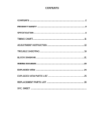
CONTENTS CONTENTS 2 PRODUCT SAFETY 3 SPECIFICATION 4 TIMING CHART 11 ADJUSTMENT INSTRUCTION 12 TROUBLE SHOOTING 16 BLOCK DIAGRAM 21 WIRING DIAGRAM 23 EXPLODED VIEW 24 EXPLODED VIEW PARTS LIST 25 REPLACEMENT PARTS LIST 26 SVC. SHEET - LG RZ-15LA70 | Service Manual - Page 3
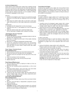
it's components from being damaged by accidental shorts of the circuitry that may be inadvertently introduced during the service operation. If any fuse (or Fusible Resistor) in this TV receiver is blown, replace it with the specified. When replacing a high wattage resistor (Oxide Metal Film Resistor - LG RZ-15LA70 | Service Manual - Page 4
receiver or any of its assemblies. 4. Unless specified otherwise in this service manual, clean electrical contacts only by applying the following mixture to the contacts device from its protective package until immediately before you are ready to install it. (Most replacement ES devices are packaged - LG RZ-15LA70 | Service Manual - Page 5
of the good copper pattern. Solder the overlapped area and clip off any excess jumper wire. At Other Connections Use the following technique to repair the defective copper pattern at connections other than IC Pins. This technique involves the installation of a jumper wire on the component side of - LG RZ-15LA70 | Service Manual - Page 6
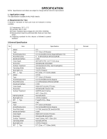
,194,277Colors 331.6(H)x254.7(V)x12.7(D) HAZE25,Hard Coating, ANTI- Glare (3H) Normally Black 4 CCFL(4 lamps) T total(Tr+Td) = 25ms CMO TFT Color LCD Module 15.0 inches(380.16mm) diagona 0. 0 304.1mm(H)x228.1mm(V)xRGB LVDS RGB 6-BIT 16,194,277Colors 331.6(H)x254.6(V)x13(D) Hard Coating, ANTI- Glare - LG RZ-15LA70 | Service Manual - Page 7
Function No. Item 1 Teletext 2 REMOCON 3 AV Input 4 S-Vedio Input 5 Component input 6 PERI TV Connector 7 RGB(VGA)Input 8 H/p input 9 PC Sound input 10 RS-232 11 Discrete IR 12 2 Carrier Stereo 13 NICAM Stereo 14 2 Carrier Dual 15 NICAM Dual 16 DW(Double Window) Mode 17 MW(Multi Window) Mode 18 - LG RZ-15LA70 | Service Manual - Page 8
6.Engineering Specification 6-1.General Specification(TV) No. Item 1 Video input applicable system 2 Receivable broadcasting system 3 RF input channel : 85% 3)Temp : -20 ~ 60 deg 4)Humidity : 85% Remark EU/Non-EU(RZ/RT) (PAL Market) 7)NTSC Area(RM) PAL FRANCE NTSC JAPAN PAL, 200PR.(Option) NTSC - LG RZ-15LA70 | Service Manual - Page 9
Control Function Specification H/V Sync On/On Off/On On/Off Off/Off - 1: RED 3: Blue: 5: S.T(GND) 7: Green GND 9: N.C 11: ID0(GND) 13: H-Sync 15 , Inverter 3 DC Voltage, LCD Panel 4 DC Voltage, Audio Ready 9: LINE2 11: LINE3 5) 13: Line3 Ready 2: Y GND 4: Pb GND 6: Pr GND 8: LINE1 10: Line2 Ready - LG RZ-15LA70 | Service Manual - Page 10
Output S/N 10. Audio Output Level 11. Audio Output Frequency Response 12. Audio Output S/N 13. Audio Output Distortion 14. Video Input Level, R/G/B 15. Video Input Level, Component(Y, PB, PR) 16. RGB Input Resolution, Vertical 17. RGB Input Resolution, Horizontal 18. RGB Input Horizontal Frequency - LG RZ-15LA70 | Service Manual - Page 11
VIDEO SYNC TIMING CHART D C A E B > Mode 1 2 3 4 5 6 7 H/V Sync Dot Sort Polarity Clock Frequency Total Period Video Active Time (E) (A) H+ 31.468 800 640 25.175 - LG RZ-15LA70 | Service Manual - Page 12
1. Application Object This instruction is for the application to the LCD TV. 2. Adjustment 2.1 Adjustment overview The unit is set to automatically adjust using the factory automation equipment. However when errors occur, it should be adjusted manually. 2.2 Auto Gain/Offset adjustment 2.2.1 RF - LG RZ-15LA70 | Service Manual - Page 13
EU 2 4: CYRILLIC 1 5: CYRILLIC 2 6: CYRILLIC 3 7: TURKY GRE 1 8: TURKY GRE 2 9: TURKY GRE 3 10: ARAB FRAN 11: ARAB ENG 12: ARAB HEB 1 13: ARAB HEB 2 14: FARSI ENG 15: FARSI FRA 16: FARI ALL reserved - LG RZ-15LA70 | Service Manual - Page 14
User Manual Operating System: MS Windows 98, 2000, XP Port Setup: Windows 98 => Don't need setup Windows 2000, XP => Need to Port Setup. This program is available to LCD Signal Generator Control Line PARALLEL Not used RS232C C VGS A MONITOR B V-SYNC ST POWER IBM Compatible PC 15 10 5 - LG RZ-15LA70 | Service Manual - Page 15
13 ADJ 14 MPX 15 EXIT 16 APC(PSM) screen. To adjust the volume or accurately control a specific function. To set a specific delivery condition status after manufacturing the TV set. To halt the main Enables to select the sub code in the teletext mode 32 manually select the channel. Shortcut keys - LG RZ-15LA70 | Service Manual - Page 16
TROUBLESHOOTING No power (LED indicator off) :[A]Process Check 15V or 5V of Lips Check short of main B/D Fail or Change Lips Pass Check Output of IC1107, - LG RZ-15LA70 | Service Manual - Page 17
No Raster :[B]Process Check LED Status on display unit Fail Repeat A PROCESS Check L900,L901 L902,L903 Fail Pass Check the input/ Output of IC901 Fail Pass Check inverter Connector or inverter Fail Pass Check panel link Cable or module Fail Pass Check input source cable and jack - LG RZ-15LA70 | Service Manual - Page 18
No Raster on Component signal Repeat [A] Process Pass Check the signal of L1200, L1202, L1203 Fail Pass Check the input/ output of IC1 Fail Check the input/output of IC800, IC851 Fail Pass Check the input/ output of IC901 Fail Pass Check input source cable and jack Check JA1200 or - LG RZ-15LA70 | Service Manual - Page 19
No Raster on AV Signal (Video, S-Video) No Raster on TV(RF) signal Repeat [A] Process Pass Check the output of Fail TU1000 Check 5V, 33V of TU1000 Re-soldering or Fail Change the defect part Check - LG RZ-15LA70 | Service Manual - Page 20
No Sound Check the input source Pass Change source input Fail Re-soldering or Check the input/output Change the defect part of IC1 Fail Check X11 Pass Check the input/output Re-soldering or of IC100,IC101 Fail Change the defect part Pass Check the speaker Pass Check the speaker wire - LG RZ-15LA70 | Service Manual - Page 21
BLOCK DIAGRAM ML-041B Block Diagram ANALOG SIGNAL DIGITAL SIGNAL SOUND INPUT IF +,- INPUT SOUND OUTPUT POWER SIDE_AV IC100 IC101 Audio Amp L, R TC90A65F IC500 SM5301BS IC800 GM2221 IC901 TTL 1 OUT TTL 2 OUT LVDS1 OUT AT49F IC905 AT24C16 IC4 RGB OUT VCTI IC1 PC RGB M52758FP IC851 Z1000 S - LG RZ-15LA70 | Service Manual - Page 22
RF signals received from the tuner. The scaler can control timing to fit into the LCD panel, and can also control the size and position of the input signal. to generate 5V power through the regulator. 12V power is used for the LCD panel power, and 5V power is converted to 3.3V and 1.8V power - LG RZ-15LA70 | Service Manual - Page 23
H-H 100MM 3 1 1. 20P LVDS : 200MM 2. 41P TTL 3. 50P TTL : 145MM 2 4P_2.0MM H-B (17LZ50 ONLY) 6P_2.0MM H-B 600MM 6 2P_AC_SOCKET SPEAKER 18P_1.0MM FFC 54MM (RZ ONLY) 7 18P_1.0MM FFC 54MM 8 4P_2.5MM SHIELD GND: 2PIN, 4PIN 500MM 750MM RECEPTERCLE 9 SIDE AV (17LZ50 ONLY) Wiring Part List No - LG RZ-15LA70 | Service Manual - Page 24
5 1 EXPLODED VIEW 12 3 16 10 2 9 13 14 11 8 15 19 17 18 20 4 5 6 7 22 21 - LG RZ-15LA70 | Service Manual - Page 25
. BUTTON, CONTROL RZ-15LA70 ABS, HF-380 8KEY . COVER, REAR AV RZ-15LA70 ABS, HF-380 . METAL, HINGE ASSY NON 15LA70 BRACKET, STAND RU-15LA61 ML012C HIPS 60HR FRONT BRACKET, STAND RU-15LA61 ML012C HIPS 60HR REAR BRACKET, STAND RZ-15LA70 NON ABS, HF-380 . METAL, STAND SPCC(CR) SUPPORTER(LA70) METAL - LG RZ-15LA70 | Service Manual - Page 26
REPLACEMENT PARTS LIST For Capacitor & Resistors, the charactors at 2nd and 3rd digit in the P/No. means as follows; CC, CX, CK, CN, CH : Ceramic CQ : Polyestor CE : Electrolytic CF : Fixed Film RD : Carbon Film RS : Metal Oxide Film RN : Metal Film RH : CHIP, Metal Glazed(Chip) RR : Drawing - LG RZ-15LA70 | Service Manual - Page 27
*S *AL LOC. NO. PART NO. DATE: 2004. 06.03. DESCRIPTION / SPECIFICATION C118 C12 C125 C126 C200 C22 C23 C24 C25 C26 C27 C28 C29 C3 C30 C31 C32 C33 C34 C35 C37 C40 C42 C45 C52 C67 C75 C800 C801 C802 C807 C811 C816 C82 C861 C865 C875 C900 C901 C902 C903 C904 C905 C906 C911 C912 C913 C914 C915 C916 - LG RZ-15LA70 | Service Manual - Page 28
*S *AL LOC. NO. PART NO. DATE: 2004. 06.03. DESCRIPTION / SPECIFICATION ZD206 ZD207 ZD208 ZD209 ZD211 0DZ510009EE 0DZ510009EE 0DZ510009EE 0DZ510009EE 0DZ510009EE UDZ S 5.1B TP ROHM-K SOD323 UDZ S 5.1B TP ROHM-K SOD323 UDZ S 5.1B TP ROHM-K SOD323 UDZ S 5.1B TP ROHM-K SOD323 UDZ S 5.1B TP ROHM-K - LG RZ-15LA70 | Service Manual - Page 29
*S *AL LOC. NO. PART NO. DATE: 2004. 06.03. DESCRIPTION / SPECIFICATION R204 R211 R212 R213 R214 R215 R216 R217 R36 R57 R59 R6 R817 R818 R9 R903 R908 R910 R915 R934 R961 R985 R989 R994 R995 R999 R1 R10 R1001 R1002 R1003 R1005 R1014 R11 R1105 R1106 R1107 R1150 R1152 R12 R124 R125 R127 R128 R129 R13 - LG RZ-15LA70 | Service Manual - Page 30
TU1000 6700VS0003A X11 6202VDT002E X900 6202VDT002B PEJ012C PARK ELEC H=6.5 STER TAEW-G051D LG INOTEK MULTI V SX-1SMD SUNNY RADIAL 2025000 SX-1 SUNNY SC14.3MHZ +/- 30 CONTROL BOARD R2200 0RN1101F409 R2201 0RN8200F409 R2202 0RN5600F409 R2203 0RN4700F409 R2204 0RN3900F409 R2205 0RN3300F409 - LG RZ-15LA70 | Service Manual - Page 31
*S *AL LOC. NO. PART NO. DATE: 2004. 06.03. DESCRIPTION / SPECIFICATION ZD1213 0DZ620009HB UDZ S 6.2B TP ROHM SOD323 20 ZD1214 0DZ620009HB UDZ S 6.2B TP ROHM SOD323 20 JA1200 381-091C UPJ-R1-019 UGCOM 21PIN W/SHI JA1201 6613V00008F PMJ014F PARK ELEC E/P(ST)+S- P1200 6602T25008C SMW250-04 - LG RZ-15LA70 | Service Manual - Page 32
- LG RZ-15LA70 | Service Manual - Page 33
- LG RZ-15LA70 | Service Manual - Page 34
P/NO : 3828TSL103F Jun., 2004 Printed in Korea
-
 1
1 -
 2
2 -
 3
3 -
 4
4 -
 5
5 -
 6
6 -
 7
7 -
8
-
9
-
10
-
11
-
12
-
13
-
14
-
15
-
16
-
17
-
18
-
19
-
20
-
21
-
22
-
23
-
24
-
25
-
26
-
27
-
28
-
29
-
30
-
31
-
32
-
33
-
34
 |
 |
R
LCD TV
SERVICE MANUAL
CAUTION
BEFORE SERVICING THE CHASSIS,
READ THE SAFETY PRECAUTIONS IN THIS MANUAL.
CHASSIS : ML-041B
MODEL: RZ-15LA70
(RZ-15LA70 Rev A)
website:http://biz.LGservice.com
*(
) ID LABEL Model No.
*Same looking with new chassis
*Issue Date; 2004. 06