Lenovo 81713GU User Manual - Page 30
Installing, memory
 |
View all Lenovo 81713GU manuals
Add to My Manuals
Save this manual to your list of manuals |
Page 30 highlights
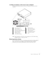
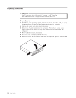
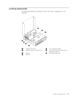
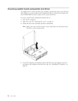
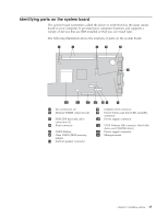
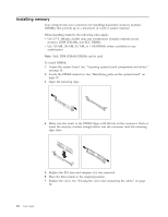
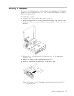
Installing memory Your computer has two connectors for installing dual inline memory modules (DIMMs) that provide up to a maximum of 2 GB of system memory. When installing memory, the following rules apply: v Use 2.5 V, 184-pin, double data rate synchronous dynamic random access memory (DDR SDRAM), non-ECC DIMMs. v Use 128 MB, 256 MB, 512 MB, or 1 GB DIMMs (when available) in any combination. Note: Only DDR SDRAM DIMMs can be used. To install DIMMs: 1. Access the system board. See "Accessing system board components and drives" on page 14. 2. Locate the DIMM connectors. See "Identifying parts on the system board" on page 15. 3. Open the retaining clips. 4. Make sure the notch in the DIMM aligns with the tab on the connector. Push or insert the memory module straight down into the connector until the retaining clips close. 5. Replace the PCI riser and adapters if it was removed. 6. Place the drives back to the original position. 7. Replace the cover. See "Closing the cover and connecting the cables" on page 24. 16 User Guide
-
 1
1 -
2
-
3
-
4
-
5
-
6
-
7
-
8
-
9
-
10
-
11
-
12
-
13
-
14
-
15
-
16
-
17
-
18
-
19
-
20
-
21
-
22
-
23
-
24
-
 25
25 -
 26
26 -
 27
27 -
 28
28 -
 29
29 -
 30
30 -
 31
31 -
 32
32 -
 33
33 -
 34
34 -
 35
35 -
36
-
37
-
38
-
39
-
40
-
41
-
42
-
43
-
44
-
45
-
46
-
47
-
48
-
49
-
50
-
51
-
52
-
53
-
54
-
55
-
56
-
57
-
58
-
59
-
60
 |
 |