Lenovo B460 Lenovo B460 Hardware Maintenance Manual V2.0 - Page 58
Fan assembly and Heat Sink assembly
 |
View all Lenovo B460 manuals
Add to My Manuals
Save this manual to your list of manuals |
Page 58 highlights
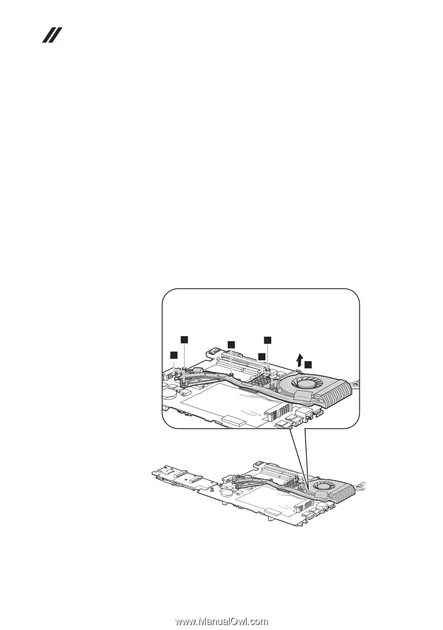
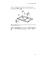
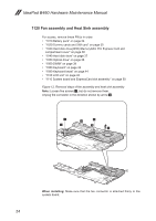
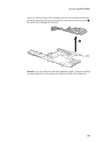
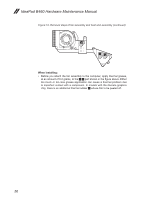
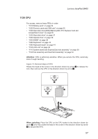
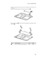
IdeaPad B460 Hardware Maintenance Manual 1120 Fan assembly and Heat Sink assembly For access, remove these FRUs in order: •• "1010 Battery pack" on page 34 •• "1020 Dummy cards and SIM card" on page 35 •• "1030 Hard disk drive(HDD)/Memory/Mini PCI Express Card slot compartment cover" on page 36 •• "1040 Hard disk drive" on page 37 •• "1050 Optical drive" on page 38 •• "1060 DIMM" on page 39 •• "1080 Keyboard" on page 42 •• "1090 Keyboard bezel" on page 44 •• "1100 LCD unit" on page 48 •• "1110 System board and ExpressCard slot assembly" on page 50 Figure 12. Removal steps of fan assembly and heat sink assembly Note: Loosen five screws 1, but do not remove them. Unplug the connector in the direction shown by arrow 2. 1 1 1 1 1 2 When installing: Make sure that the fan connector is attached firmly to the system board. 54
-
 1
1 -
2
-
3
-
4
-
5
-
6
-
7
-
8
-
9
-
10
-
11
-
12
-
13
-
14
-
15
-
16
-
17
-
18
-
19
-
20
-
21
-
22
-
23
-
24
-
25
-
26
-
27
-
28
-
29
-
30
-
31
-
32
-
33
-
34
-
35
-
36
-
37
-
38
-
39
-
40
-
41
-
42
-
43
-
44
-
45
-
46
-
47
-
48
-
49
-
50
-
51
-
52
-
 53
53 -
 54
54 -
 55
55 -
 56
56 -
 57
57 -
 58
58 -
 59
59 -
 60
60 -
 61
61 -
 62
62 -
 63
63 -
64
-
65
-
66
-
67
-
68
-
69
-
70
-
71
-
72
-
73
-
74
-
75
-
76
-
77
-
78
-
79
-
80
-
81
-
82
-
83
-
84
-
85
-
86
-
87
-
88
 |
 |