Lenovo B460 Lenovo B460 Hardware Maintenance Manual V2.0 - Page 60
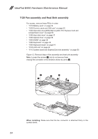
Removal steps of fan assembly and heat sink assembly continued
 |
View all Lenovo B460 manuals
Add to My Manuals
Save this manual to your list of manuals |
Page 60 highlights
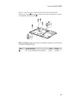
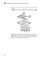
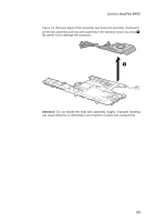
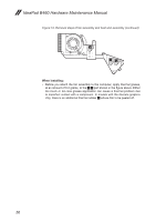
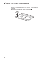
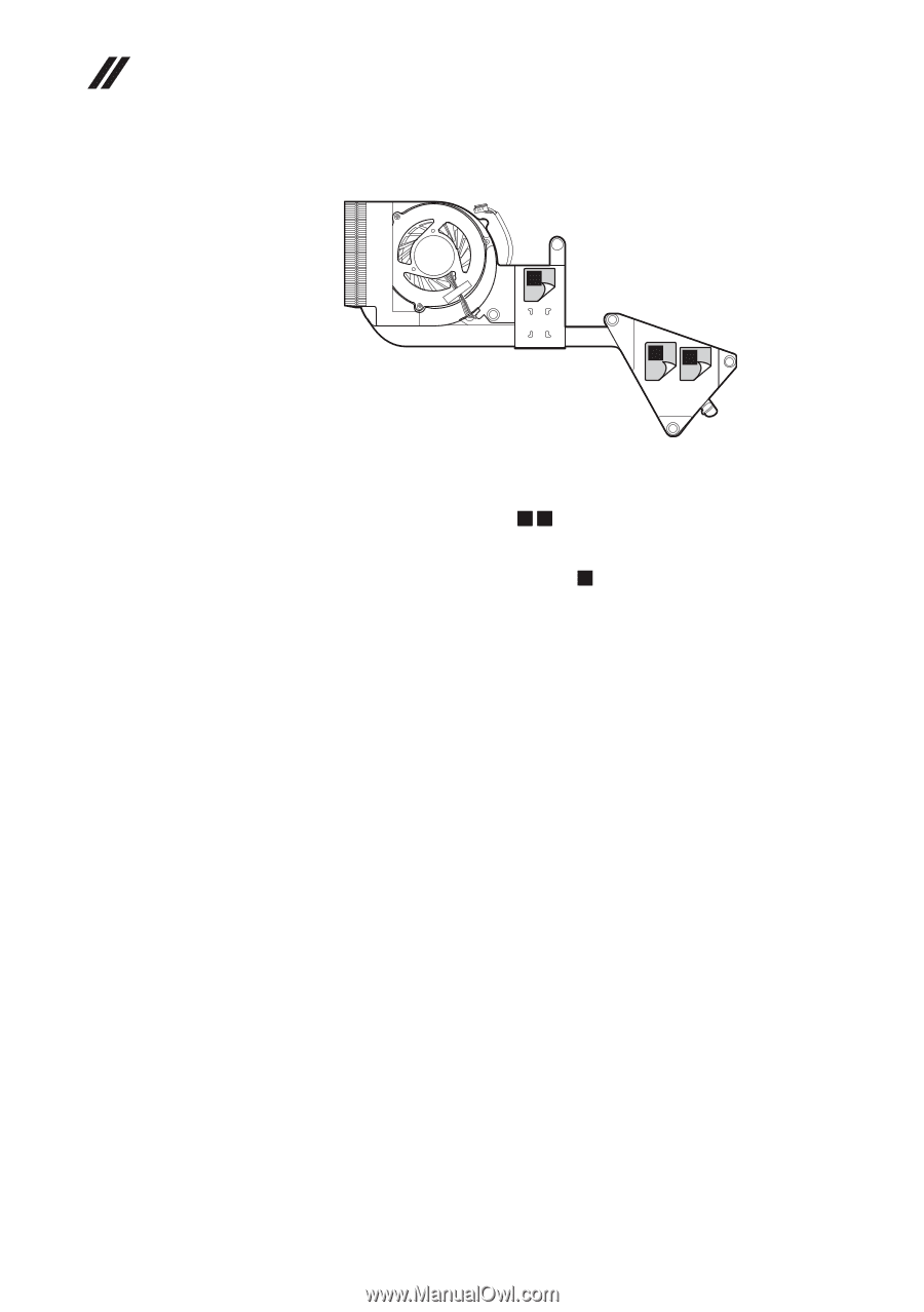
IdeaPad B460 Hardware Maintenance Manual Figure 12. Removal steps of fan assembly and heat sink assembly (continued) c ab When installing: •• Before you attach the fan assembly to the computer, apply thermal grease, at an amount of 0.2 grams, to the a b part shown in the figure above. Either too much or too less grease application can cause a thermal problem due to imperfect contact with a component. In models with the discrete graphics chip, there is an additional thermal rubber c whose film to be peeled off. 56
-
 1
1 -
2
-
3
-
4
-
5
-
6
-
7
-
8
-
9
-
10
-
11
-
12
-
13
-
14
-
15
-
16
-
17
-
18
-
19
-
20
-
21
-
22
-
23
-
24
-
25
-
26
-
27
-
28
-
29
-
30
-
31
-
32
-
33
-
34
-
35
-
36
-
37
-
38
-
39
-
40
-
41
-
42
-
43
-
44
-
45
-
46
-
47
-
48
-
49
-
50
-
51
-
52
-
53
-
54
-
 55
55 -
 56
56 -
 57
57 -
 58
58 -
 59
59 -
 60
60 -
 61
61 -
 62
62 -
 63
63 -
 64
64 -
 65
65 -
66
-
67
-
68
-
69
-
70
-
71
-
72
-
73
-
74
-
75
-
76
-
77
-
78
-
79
-
80
-
81
-
82
-
83
-
84
-
85
-
86
-
87
-
88
 |
 |
56
IdeaPad B460 Hardware Maintenance Manual
Figure 12. Removal steps of fan assembly and heat sink assembly (continued)
c
a
b
When installing:
Before you attach the fan assembly to the computer, apply thermal grease,
•
at an amount of 0.2 grams, to the
a
b
part shown in the figure above. Either
too much or too less grease application can cause a thermal problem due
to imperfect contact with a component. In models with the discrete graphics
chip, there is an additional thermal rubber
c
whose film to be peeled off.