Lenovo B575 Hardware Maintenance Manual
Lenovo B575 Manual
 |
View all Lenovo B575 manuals
Add to My Manuals
Save this manual to your list of manuals |
Lenovo B575 manual content summary:
- Lenovo B575 | Hardware Maintenance Manual - Page 1
Lenovo B575 Hardware Maintenance Manual - Lenovo B575 | Hardware Maintenance Manual - Page 2
using this information and the product it supports, be sure to read the general information under "Notices" on page 81. First Edition (April 2011) © Copyright Lenovo 2011. All rights reserved. LENOVO products, data, computer software, and services have been developed exclusively at private expense - Lenovo B575 | Hardware Maintenance Manual - Page 3
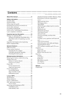
Supervisor password 24 Power management 25 Screen blank mode 25 Sleep (standby) mode 25 Hibernation mode 26 Lenovo B575 27 Specifications 27 Status indicators 29 Fn key combinations 31 FRU replacement notices 32 Screw notices 32 Removing and replacing an FRU 33 1010 Battery pack 34 1020 - Lenovo B575 | Hardware Maintenance Manual - Page 4
for the following Lenovo product: Lenovo B575 Use this manual to troubleshoot problems. The manual is divided into the following sections: • The common sections provide general information, guidelines, and safety information required for servicing computers. • The product-specific section includes - Lenovo B575 | Hardware Maintenance Manual - Page 5
the following safety information that you need to get familiar with before you service a Lenovo computer: • "General safety" on page 2 • "Electrical safety" on page 3 • "Safety inspection guide" on page 5 • "Handling devices that are sensitive to electrostatic discharge" on page 6 • "Grounding - Lenovo B575 | Hardware Maintenance Manual - Page 6
Lenovo B575 Hardware Maintenance Manual General safety Follow these rules below to ensure general safety: • Observe a good housekeeping in the area where the machines are put during and after the maintenance. • When lifting any heavy object: 1. Make sure that you can stand safely without slipping. - Lenovo B575 | Hardware Maintenance Manual - Page 7
special safety precautions when you work with very high voltages; instructions for these precautions are in the safety sections of maintenance electrical hand tools for safe operational condition. • Do not use worn or broken tools and testers. • Never assume that power has been disconnected from - Lenovo B575 | Hardware Maintenance Manual - Page 8
Lenovo B575 Hardware Maintenance Manual • Always look carefully for possible hazards in your work area. Examples of these hazards are moist floors, nongrounded power extension cables, power surges, and missing safety grounds. • Do not touch live electrical circuits with the reflective surface of a - Lenovo B575 | Hardware Maintenance Manual - Page 9
-Lenovo features or options not covered by this inspection guide. service task. Begin the checks with the power off, and the power cord disconnected. Checklist: 1. Check exterior covers for damage (loose, broken, or sharp edges). 2. Turn off the computer. Disconnect the power cord. 3. Check the power - Lenovo B575 | Hardware Maintenance Manual - Page 10
Lenovo B575 Hardware Maintenance Manual Handling devices that are sensitive to electrostatic discharge Any computer part containing transistors or , such as those listed below, to provide protection that meets the specific service requirement. Notes: The use of a grounding system to guard against - Lenovo B575 | Hardware Maintenance Manual - Page 11
The safety notices in this section are provided in English, French, German, Hebrew, Italian, Japanese, and Spanish. Safety notice 1 Before the computer is powered on after FRU replacement, make sure all screws, springs, and other small parts are in place and are not left loose inside the - Lenovo B575 | Hardware Maintenance Manual - Page 12
Lenovo B575 Hardware Maintenance Manual Safety notice 2 DANGER Some standby batteries contain a small amount of nickel and cadmium. Do not disassemble a standby battery, recharge it, throw it into fire or water, or short-circuit it. Dispose of the battery as required by local ordinances or - Lenovo B575 | Hardware Maintenance Manual - Page 13
pack as required by local ordinances or regulations. Use only the battery in the appropriate parts listing when replacing the battery pack. Use of an incorrect battery can result in ignition or explosion of the battery. La batterie contient du nickel. Ne la démontez pas, ne l'exposez ni au feu - Lenovo B575 | Hardware Maintenance Manual - Page 14
Lenovo B575 Hardware Maintenance Manual Safety notice 4 DANGER The lithium battery can cause a fire, an explosion, or a severe burn. Do not recharge it, remove its polarized connector, disassemble it, heat it above 100°C (212°F), incinerate it, - Lenovo B575 | Hardware Maintenance Manual - Page 15
Entsorgung die örtlichen Bestimmungen für Sondermüll beachten. Der LCD-Bildschirm besteht aus Glas und kann zerbrechen, wenn er unsachgemäß behandelt wird oder der Computer auf den Boden fällt. Wenn der Bildschirm beschädigt ist und die darin befindliche Flüssigkeit in Kontakt mit Haut und Augen ger - Lenovo B575 | Hardware Maintenance Manual - Page 16
Lenovo B575 Hardware Maintenance Manual Safety notice 6 DANGER To avoid shock, do not remove the plastic cover , um brennbare Materialien zu entzünden oder Verletzungen bei Personen hervorzurufen. Sebbene le batterie di alimentazione siano a basso voltaggio, una batteria in corto circuito o a massa - Lenovo B575 | Hardware Maintenance Manual - Page 17
Safety information Safety notice 8 DANGER Before removing any FRU, turn off the computer, unplug all power cords from electrical outlets, remove the battery pack, and then disconnect any interconnecting cables. Avant de retirer une unité remplaçable en clientèle, mettez le système hors tension, dé - Lenovo B575 | Hardware Maintenance Manual - Page 18
Lenovo B575 Hardware Maintenance Manual Laser compliance statement Some models of Lenovo computer are equipped from the factory with o l'esecuzione di procedure diverse da quelle specificate possono provocare l'esposizione a. El uso de serviceable parts inside those drives. Do not open. 14 - Lenovo B575 | Hardware Maintenance Manual - Page 19
Safety information A CD-ROM drive, a DVD-ROM drive, or any other storage device installed may contain an embedded Class 3A or Class 3B laser diode. Note the following: DANGER Emits visible and invisible laser radiation when open. Do not stare into the beam, do not view directly with optical - Lenovo B575 | Hardware Maintenance Manual - Page 20
BIOS and device drivers are posted on the customer support site: http://consumersupport.lenovo.com/. Strategy for replacing FRUs Before replacing parts: Make sure that all software fixes, drivers, and BIOS downloads are installed before replacing any FRUs listed in this manual. After a system board - Lenovo B575 | Hardware Maintenance Manual - Page 21
Use the following strategy to prevent unnecessary expense for replacing and servicing FRUs: • If you are instructed to replace an FRU, but the replacement does not solve the problem, reinstall the original FRU before you continue. • Some computers have both a processor board and a system board. If - Lenovo B575 | Hardware Maintenance Manual - Page 22
Lenovo B575 Hardware Maintenance Manual Important information about replacing RoHS compliant FRUs support Lenovo's requirements and schedule in the EU. Products sold in 2005 and 2006 will contain some RoHS compliant FRUs. The following statement pertains to these products and any product Lenovo - Lenovo B575 | Hardware Maintenance Manual - Page 23
Power system checkout" on page 21 Before you go to the checkout, make sure to read the following important notes: Important notes: • Only certified trained personnel can service the computer. • Before replacing or software errors. Consider replacing an FRU only when a problem recurs. If you suspect - Lenovo B575 | Hardware Maintenance Manual - Page 24
computer password (making the computer unusable) • Sticky keys caused by spilling a liquid onto the keyboard • Use of an incorrect AC adapter on laptop products The following symptoms might indicate damage caused by nonwarranted activities: • Missing parts might be a symptom of unauthorized service - Lenovo B575 | Hardware Maintenance Manual - Page 25
from the one you are servicing. 3. If the voltage is not correct, replace the AC adapter. 4. If the voltage is acceptable, do the following: • Replace the system board. • If the problem continues, go to "Lenovo B575" on page 27. Note: Noise from the AC adapter does not always indicate a defect - Lenovo B575 | Hardware Maintenance Manual - Page 26
Lenovo B575 Hardware Maintenance Manual Perform operational charging. If the battery status indicator or icon does not light on, remove the battery pack and let it return to room temperature. Reinstall the battery pack. If the charge indicator or icon is still off, replace the battery pack. If the - Lenovo B575 | Hardware Maintenance Manual - Page 27
contents by using OneKey Recovery" on page 23 • "Passwords" on page 24 • "Power management" on page 25 Restoring the factory contents by using OneKey Recovery Restore of factory default The Lenovo B575 computers come with pre-installed OneKey Rescue System. In order to save application files and the - Lenovo B575 | Hardware Maintenance Manual - Page 28
Lenovo B575 Hardware Maintenance Manual When you use the recovery discs to boot your computer appears on the screen whenever the computer is turned on. The computer does not start servicer, there is no service procedure to reset the password. The system board must be replaced for a scheduled fee. 24 - Lenovo B575 | Hardware Maintenance Manual - Page 29
Related service information Power management Note: Power management modes are not supported for APM operating system. To reduce power consumption, the computer has three power management modes: screen blank, sleep (standby), and hibernation. Screen blank mode If the time set on the "Turn off monitor - Lenovo B575 | Hardware Maintenance Manual - Page 30
Lenovo B575 Hardware Maintenance Manual Hibernation mode In hibernation mode, the following occurs: • The system status, RAM, VRAM, and setup data are stored on the hard disk. • The system is powered off. To cause the computer to enter hibernation mode, follow the steps below: • If you are using the - Lenovo B575 | Hardware Maintenance Manual - Page 31
Lenovo B575 Lenovo B575 This chapter presents the following product-specific service references and product-specific parts information: • "Specifications" on page 27 • "Status indicators" on page 29 • "Fn key combinations" on page 31 • "FRU replacement notices" on page 32 • "Removing and replacing - Lenovo B575 | Hardware Maintenance Manual - Page 32
Lenovo B575 Hardware Maintenance Manual Table 1. Specifications (continued) Feature Description MODEM slot • N/A Audio • 1/8" Stereo Headphone Output Jack • 1/8" Microphone Input Combo Jack • 0.3Million pixels Battery • 48WH, 6 cell cylindrical Li-ion Battery AC adapter • 65W Pre- - Lenovo B575 | Hardware Maintenance Manual - Page 33
Lenovo B575 Status indicators The system status indicators below show the computer status: 45 6 1 23 Table 2. Status indicators Indicator Meaning a Caps lock White: Caps Lock mode is enabled. You can enter all alphabetic characters (A-Z) in uppercase without pressing the Shift key. To enable - Lenovo B575 | Hardware Maintenance Manual - Page 34
Lenovo B575 Hardware Maintenance Manual d Power on e Battery status f Wireless status White: System is enabled. Blinking white: System is in sleep mode. off: System is in hibernate mode or shut down. Blinking amber: (500ms off/1s on) The remaining power of the battery is less than 5% of its - Lenovo B575 | Hardware Maintenance Manual - Page 35
Lenovo B575 Fn key combinations The following table shows the function of each combination of Fn with a function key. Table 4. Fn key combinations Key combination Description Fn + Esc: Turn on/off the integrated camera. Fn + F1: Enter sleep mode. Fn + F2: Turn on/off the backlight of the - Lenovo B575 | Hardware Maintenance Manual - Page 36
Lenovo B575 Hardware Maintenance Manual FRU replacement notices This section presents notices related to removing and replacing parts. Read this section carefully before replacing any FRU. Screw notices Loose screws can cause a reliability problem. In the Lenovo computer, this problem driver If - Lenovo B575 | Hardware Maintenance Manual - Page 37
Lenovo B575 Removing and replacing an FRU This section presents exploded figures with the instructions to indicate how to remove and replace the FRU. Make sure to observe the following general rules: 1. Do not attempt to service any computer unless you have been trained and certified. An untrained - Lenovo B575 | Hardware Maintenance Manual - Page 38
Lenovo B575 Hardware Maintenance Manual 1010 Battery pack DANGER Only use the battery specified in the parts list for your computer. Any other battery could ignite or explode. Figure 1. Removal steps of battery pack Unlock the battery release lever a. Holding the battery release lever in the - Lenovo B575 | Hardware Maintenance Manual - Page 39
Lenovo B575 1020 Dummy card For access, remove this FRU: • "1010 Battery pack" on page 34 Figure 2. Removal steps of dummy cards Remove the dummy card in the direction shown by arrows a b . 1 2 35 - Lenovo B575 | Hardware Maintenance Manual - Page 40
Lenovo B575 Hardware Maintenance Manual 1030 Hard disk drive(HDD)/Memory/Mini PCI Express Card slot compartment cover For access, remove this FRU: • "1010 Battery pack" on page 34 Figure 3. Removal steps of HDD/Memory/Mini PCI Express Card slot compartment cover Loosen five screws a , then remove - Lenovo B575 | Hardware Maintenance Manual - Page 41
Lenovo B575 1040 Hard disk drive For access, remove these FRUs in order: • "1010 Battery pack" on page 34 • "1030 Hard disk it if possible. • Never remove the drive while the system is operating or is in suspend mode. Figure 4. Removal steps of hard disk drive Remove the screw a and pull the tab up - Lenovo B575 | Hardware Maintenance Manual - Page 42
Lenovo B575 Hardware Maintenance Manual 1050 Optical drive For access, remove this FRU: • "1010 Battery pack" on page 34 • "1030 Hard disk drive(HDD)/Memory/Mini PCI Express Card slot compartment cover" on page 36 Figure 4. Removal steps of optical - Lenovo B575 | Hardware Maintenance Manual - Page 43
Lenovo B575 1060 DIMM For access, remove these FRUs in order: • "1010 Battery pack" on page 34 • "1030 DIMM in the direction shown by arrow b. $ $ % Note: If only one DIMM is used on the computer you are servicing, the card must be installed in SLOT-0 ( : lower slot), but not in SLOT-1 ( : upper - Lenovo B575 | Hardware Maintenance Manual - Page 44
Lenovo B575 Hardware Maintenance Manual 1070 PCI Express Mini Card for wireless LAN/WAN For access, remove these FRUs in order: • "1010 Battery pack" on , white) a, and then remove the screw b. In step a, unplug the jacks by using the removal tool antenna RF connector (P/N: 08K7159), or pick up the - Lenovo B575 | Hardware Maintenance Manual - Page 45
Lenovo B575 Figure 7. Removal steps of PCI Express Mini Card for wireless LAN/WAN (continued) Remove the card in the direction shown by arrow c . 3 When installing: • In models with a wireless LAN card that has two antenna connectors, plug the black cable (1st) (MAIN) into the jack labeled 1, and - Lenovo B575 | Hardware Maintenance Manual - Page 46
Lenovo B575 Hardware Maintenance Manual 1080 Keyboard For access, remove this FRU: • "1010 Battery pack" on page 34 • "1030 Hard disk drive(HDD)/Memory/Mini PCI Express Card slot compartment cover" on page 36 Figure 8. Removal steps of keyboard - Lenovo B575 | Hardware Maintenance Manual - Page 47
Lenovo B575 Figure 8. Removal steps of keyboard (continued) Loosen the keyboard with fingers in the direction shown by arrows b. 2 43 - Lenovo B575 | Hardware Maintenance Manual - Page 48
Lenovo B575 Hardware Maintenance Manual Figure 8. Removal steps of keyboard (continued) Lift the keyboard a little c, and then detach the connector in the direction shown by arrows d e. 3 4 5 When installing: Make sure that the FPC connector is attached firmly. 44 - Lenovo B575 | Hardware Maintenance Manual - Page 49
Lenovo B575 1090 Keyboard bezel For access, remove these FRUs in order: • "1010 Battery pack" on page 34 • "1030 Hard disk drive(HDD)/Memory/Mini PCI Express Card slot compartment cover" on page 36 • "1050 Optical drive" on page - Lenovo B575 | Hardware Maintenance Manual - Page 50
Lenovo B575 Hardware Maintenance Manual Figure 9. Removal steps of keyboard bezel (continued) Remove the screw c. 3 Step c Screw (quantity) Color M2 × 6 mm, flat-head, nylok-coated (1) Black Torque 2.5 kgfcm 46 - Lenovo B575 | Hardware Maintenance Manual - Page 51
Lenovo B575 Figure 9. Removal steps of keyboard bezel (continued) Detach five FPC connectors in the direction shown by arrows d e. Unplug the microphone connector in the direction shown - Lenovo B575 | Hardware Maintenance Manual - Page 52
Lenovo B575 Hardware Maintenance Manual Figure 9. Removal steps of keyboard bezel (continued) Remove the keyboard bezel in the direction shown by arrow g. 7 Remove the screw h, and then remove the power board i. 8 9 Step h Screw (quantity) Color M2 × 3.5 mm, flat-head, nylok-coated (1) Black - Lenovo B575 | Hardware Maintenance Manual - Page 53
Lenovo B575 1100 System board Important notices for handling the system board: When handling surface such as an ESD mat or conductive corrugated material. For access, remove these FRUs in order: • "1010 Battery pack" on page 34 • "1020 Dummy card" on page 35 • "1030 Hard disk drive(HDD)/Memory/Mini - Lenovo B575 | Hardware Maintenance Manual - Page 54
Lenovo B575 Hardware Maintenance Manual Figure 10. Removal steps of system board Remove four screws a. Unplug the LCD connector in the direction shown by arrow b, and four connectors in the - Lenovo B575 | Hardware Maintenance Manual - Page 55
Lenovo B575 Figure 10. Removal steps of system board (continued) Remove the system board in the direction shown by radio switch as shown in , and make sure that both of the audio jack and the microphone jack are attached to the holes on the base cover as shown in . Improper placement of the switch - Lenovo B575 | Hardware Maintenance Manual - Page 56
Lenovo B575 Hardware Maintenance Manual 1110 LCD unit For access, remove these FRUs in order: • "1010 Battery pack" on page 34 • "1020 subjected to any tension. Tension could cause the cables to be damaged by the cable guides, or a wire to be broken. • Make sure that the LCD connector is attached - Lenovo B575 | Hardware Maintenance Manual - Page 57
Lenovo B575 Figure 11. Removal steps of LCD unit (continued) Remove the LCD unit in the direction shown by arrows c. 3 3 53 - Lenovo B575 | Hardware Maintenance Manual - Page 58
Lenovo B575 Hardware Maintenance Manual 1120 Fan assembly and Heat Sink assembly For access, remove these FRUs in order: • "1010 Battery pack" on page 34 • "1020 Dummy card" on page 35 • "1030 Hard disk drive(HDD)/Memory/Mini PCI Express Card slot compartment cover" on page - Lenovo B575 | Hardware Maintenance Manual - Page 59
Lenovo B575 Figure 12. Removal steps of fan assembly and heat sink assembly (continued) Loosen five screws b . 2 2 2 2 2 Lift the fan assembly and heat sink assembly in the direction shown by arrow c. Be careful not to damage the connector. 3 55 - Lenovo B575 | Hardware Maintenance Manual - Page 60
Lenovo B575 Hardware Maintenance Manual 1130 Base cover, speakers and bluetooth card For access, remove these FRUs in order: • "1010 Battery pack" on page 34 • "1020 Dummy card" on page 35 • "1030 Hard disk drive(HDD)/Memory/Mini PCI Express Card slot compartment cover" on page - Lenovo B575 | Hardware Maintenance Manual - Page 61
Lenovo B575 Note: Applying labels to the base cover The new base cover FRU is shipped with a kit containing labels of several kinds. When you replace the base cover, you need to apply the following label: The following labels need to be peeled off from the old base cover, and need - Lenovo B575 | Hardware Maintenance Manual - Page 62
Lenovo B575 Hardware Maintenance Manual 1140 LCD front bezel For access, remove these FRUs in order: • "1010 Battery pack" on page 34 • "1020 Dummy card" on page 35 • "1030 Hard disk drive(HDD)/Memory/Mini PCI Express Card slot compartment cover" on page - Lenovo B575 | Hardware Maintenance Manual - Page 63
Lenovo B575 1150 LCD panel, LCD cable and hinges For access, remove these FRUs in order: • "1010 Battery pack" on page 34 • "1020 Dummy card" on page 35 • "1030 Hard disk drive(HDD)/Memory/Mini PCI Express Card slot compartment cover" on page - Lenovo B575 | Hardware Maintenance Manual - Page 64
Lenovo B575 Hardware Maintenance Manual Figure 16. Removal steps of LCD panel, LCD cable and hinges (continued) Remove four screws d and remove the hinges in the direction shown by arrow e. 4 5 4 4 5 4 Step d Screw (quantity) M2 × 2.5, flat-head, nylokcoated (4) Color Black Torque 1.5 kgfcm 60 - Lenovo B575 | Hardware Maintenance Manual - Page 65
Lenovo B575 Figure 16. Removal steps of LCD panel, LCD cable and hinges (continued) Note: The LCD cables are attached to the LCD panel by a metal connector. - Lenovo B575 | Hardware Maintenance Manual - Page 66
Lenovo B575 Hardware Maintenance Manual 1160 Integrated camera For access, remove these FRUs in order: • "1010 Battery pack" on page 34 • "1020 Dummy card" on page 35 • "1030 Hard disk drive(HDD)/Memory/Mini PCI Express Card slot compartment cover" on page - Lenovo B575 | Hardware Maintenance Manual - Page 67
Lenovo B575 1170 Antenna assembly and LCD cover For access, remove these FRUs in order: • "1010 Battery pack" on page 34 • "1020 Dummy tapes securing the antenna boards, release the cables from the cable guide, and then remove the antenna assembly in the direction shown by arrows a. When installing - Lenovo B575 | Hardware Maintenance Manual - Page 68
Lenovo B575 Hardware Maintenance Manual Locations Front view a Integrated camera (Select models only) b Wireless module antennas (Select models only) c Speaker d Power button e OneKey Rescue System button f Built-in microphone g System status indicators Note: For the description of each indicator, - Lenovo B575 | Hardware Maintenance Manual - Page 69
Right-side view a Headphone jack b Microphone jack c USB port d Optical drive e RJ-45 port Lenovo B575 3 2 1 5 3 4 65 - Lenovo B575 | Hardware Maintenance Manual - Page 70
Lenovo B575 Hardware Maintenance Manual Bottom and Left-side view a Kensington slot b AC power adapter jack c Fan louvers d VGA port e HDMI port (Select models only) f eSATA/USB combo port (Select models only) g USB port h Battery latch - spring loaded i Battery pack j Battery latch - manual k SIM - Lenovo B575 | Hardware Maintenance Manual - Page 71
B575 Parts list This section presents the following service parts: • "Overall" on page 68 • "LCD FRUs" on page 72 • "Keyboard" on page 74 • "Miscellaneous parts" on page 76 • "AC adapters" on page 77 • "Power cords" on page 78 Notes: • Each FRU is available for all types or models, unless specific - Lenovo B575 | Hardware Maintenance Manual - Page 72
Lenovo B575 Hardware Maintenance Manual Overall 1 2 4 e 3 df g 5 8 6 a 9 10 7 11 12 13 14 h 15 17 16 18 b c 19 20 21 68 - Lenovo B575 | Hardware Maintenance Manual - Page 73
Lenovo B575 Table 5. Parts list-Overall No. FRU FRU no. CRU ID 1 LCD unit (see "LCD FRUs" on page 72.) 2 Keyboard (see "Keyboard" on page 74.) 3 LB57 UPPER CASE ASSY W/TP&MIC 31048999 N 4 LB575 POWER BOARD 31050449 N 5 LB57 LED BOARD W/CABLE 31048995 N 6 LB575 FINGER PRINT BOARD - Lenovo B575 | Hardware Maintenance Manual - Page 74
Lenovo B575 Hardware Maintenance Manual Table 5. Parts list-Overall (continued) No. FRU FRU no USI BCM92070 BT2.1 EDR 20002326 N Flash U NB 16 Battery pack, 2200mA 6cell,48Wh 3S2P, Sanyo L09S6Y02 121001091 * 3S2P 48Wh bty(LH)Comm01 16 Battery pack, 2200mA 6cell,48Wh 3S2P, Pana L10P6Y22 3S2P 48Wh - Lenovo B575 | Hardware Maintenance Manual - Page 75
Lenovo B575 Table 5. Parts list-Overall (continued) No. FRU FRU no. 18 Hard disk drive, 500G 5400rpm SATA, Seagate 16004189 ST9500325AS 500G 9NB 18 Hard disk drive, - Lenovo B575 | Hardware Maintenance Manual - Page 76
Lenovo B575 Hardware Maintenance Manual LCD FRUs In Lenovo B575, there are following types of LCDs. • "15.6-in. HD TFT" 2 4 3 5 7 6 8 72 - Lenovo B575 | Hardware Maintenance Manual - Page 77
Lenovo B575 15.6-in. HD TFT Table 6. Parts list-15.6-in. HD TFT No. FRU 1 LB575 LCD BEZEL W/CAREMA HOLE 2 LA57 LCD SCREW HING MYLAR 3 15.6 HD - Lenovo B575 | Hardware Maintenance Manual - Page 78
Lenovo B575 Hardware Maintenance Manual Keyboard Table 7. Parts list-Keyboard Language Dafon Chicony Bulgarian Czechoslovakian International English Swiss Slovenian Icelandic Belgian Four Nordic countries Hungarian Hebrew Greek Dutch Japanese Brazilian - Lenovo B575 | Hardware Maintenance Manual - Page 79
French Russian Traditional Chinese Korean Canadian English&French Latin Portuguese Thai Turkish Spanish Italian U.K. English English Lenovo B575 P/N 25013374 25013375 25013376 25013377 25013378 25013379 25013380 25013381 25013382 25013387 25013383 25013384 25013385 25013330 25013331 25013332 - Lenovo B575 | Hardware Maintenance Manual - Page 80
Lenovo B575 Hardware Maintenance Manual Miscellaneous parts Table 8. Parts list-Miscellaneous parts FRU System miscellaneous parts: • (a) LA57 FINGER PRINT BRACKET • (b) LA57 HDD BRACKET ASSY • (c) LA57 ODD BRACKET • (d) LB57 TOUCHPD BRACKET Cable miscellaneous parts: • (e) LA57 POWER BOARD CABLE • - Lenovo B575 | Hardware Maintenance Manual - Page 81
-3-pin AC adapters FRU 65W, Delta ADP-65KH BD 20V/3.25A adapter 65W, Liteon PA-1650-56LC adapter 65W, Chicony CPA-A065 20V3.25A adapter 65W, Brazil PA-1650-52LB adapter 90W, Delta ADP-90DD BD 20V4.5A adapter 90W, Liteon PA-1900-56LC 20V4.5A adapter 90W, Chicony CPA-A090 20V4.5A adapter Lenovo B575 - Lenovo B575 | Hardware Maintenance Manual - Page 82
Lenovo B575 Hardware Maintenance Manual Power cords A Lenovo power cord for a specific country or region is usually available only in that country or region: Table 10. Parts list-3-pin power cords Region CCC • SSD YD-118-1+IEC53RVV+SSD-3-2B-1 1m CCC • LINETEK PC323+RVV300/300+LS15 1m Argentina • - Lenovo B575 | Hardware Maintenance Manual - Page 83
Table 10. Parts list-3-pin power cords (continued) Region Brazil • Longwell LP-46+H03VV-F+LS-18 1m Israel • -67+BIS+LS-18 1m Italy • Volex LP-22+H03VV-F+LS-18 1m Lenovo B575 P/N 145000564 CRU ID * 145000563 145000562 145000561 145000560 145000559 145000558 145000557 145000556 145000555 - Lenovo B575 | Hardware Maintenance Manual - Page 84
Lenovo B575 Hardware Maintenance Manual Table 10. Parts list-3-pin power cords (continued) Region Korea • Volex LP-486+KTLH03VV-F+LS-5 1m Australia • Volex LP-23A+LFC-3R+LS-18 1m Taiwan • Volex LP-71+VCTF+LS- - Lenovo B575 | Hardware Maintenance Manual - Page 85
the operation of any other product, program, or service. Lenovo may have patents or pending patent applications covering support applications where malfunction may result in injury or death to persons. The information contained in this document does not affect or change Lenovo product specifications - Lenovo B575 | Hardware Maintenance Manual - Page 86
Lenovo B575 Hardware Maintenance Manual Any specific environment. Trademarks The following terms are either registered trademarks or trademarks of Lenovo in the United States and/or other countries: Lenovo® Lenovo logo® IdeaPad® VeriFace® OneKey Rescue® (OneKey Recovery, OneKey Antivirus) APS® Power
-
 1
1 -
 2
2 -
 3
3 -
 4
4 -
 5
5 -
 6
6 -
 7
7 -
8
-
9
-
10
-
11
-
12
-
13
-
14
-
15
-
16
-
17
-
18
-
19
-
20
-
21
-
22
-
23
-
24
-
25
-
26
-
27
-
28
-
29
-
30
-
31
-
32
-
33
-
34
-
35
-
36
-
37
-
38
-
39
-
40
-
41
-
42
-
43
-
44
-
45
-
46
-
47
-
48
-
49
-
50
-
51
-
52
-
53
-
54
-
55
-
56
-
57
-
58
-
59
-
60
-
61
-
62
-
63
-
64
-
65
-
66
-
67
-
68
-
69
-
70
-
71
-
72
-
73
-
74
-
75
-
76
-
77
-
78
-
79
-
80
-
81
-
82
-
83
-
84
-
85
-
86
 |
 |

Lenovo B575
Hardware
Maintenance
Manual