Lenovo C560 Lenovo C560 Hardware Maintenance Manual
Lenovo C560 Manual
 |
View all Lenovo C560 manuals
Add to My Manuals
Save this manual to your list of manuals |
Lenovo C560 manual content summary:
- Lenovo C560 | Lenovo C560 Hardware Maintenance Manual - Page 1
Lenovo C560Hardware Maintenance Manual ideaideaideaCentreidea Machine Types: 10150/F0AE [C560] - Lenovo C560 | Lenovo C560 Hardware Maintenance Manual - Page 2
- Lenovo C560 | Lenovo C560 Hardware Maintenance Manual - Page 3
Lenovo C560 Hardware Maintenance Manual Machine Types: 10150/F0AE [C560] - Lenovo C560 | Lenovo C560 Hardware Maintenance Manual - Page 4
Second Edition (October 2013)30th © Copyright Lenovo 2013. LIMITED AND RESTRICTED RIGHTS NOTICE: If data or software are delivered pursuant a General Services Administration "GSA" contract, use, reproduction, or disclosure is subject to restrictions set forth in Contract No. GS-35F-05925 - Lenovo C560 | Lenovo C560 Hardware Maintenance Manual - Page 5
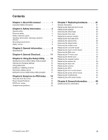
disabling a device 15 Selecting a startup device 16 Exiting the Lenovo BIOS Setup Utility program . . 17 Chapter 6. Symptom-to-FRU Index . . 19 Hard disk drive boot error 19 Power Supply Problems 19 POST error codes 20 Undetermined problems 20 Chapter 7. Replacing hardware . . . . 21 General - Lenovo C560 | Lenovo C560 Hardware Maintenance Manual - Page 6
iv Lenovo C560Hardware Maintenance Manual - Lenovo C560 | Lenovo C560 Hardware Maintenance Manual - Page 7
Chapter 1. About this manual This manual contains service and reference information for Lenovo C560 All-In-One computers listed on the cover. It is intended only for trained servicers who are familiar with Lenovo computer products. Before servicing a Lenovo product, be sure to read the Safety - Lenovo C560 | Lenovo C560 Hardware Maintenance Manual - Page 8
2 Lenovo C560Hardware Maintenance Manual - Lenovo C560 | Lenovo C560 Hardware Maintenance Manual - Page 9
parts in a safe place, away from all personnel, while you are servicing the computer. • Keep your tool case away from areas that people may walk through to ensure no-one power cords, telecommunication cables, network cables, and modem cables before you open the computer covers, unless instructed - Lenovo C560 | Lenovo C560 Hardware Maintenance Manual - Page 10
mirror. This surface is conductive, and touching a live circuit can cause personal injury and damage to the computer. • Do not service the following parts with the power on when they are removed from their normal operating positions in a computer: - Power supply units - Pumps - Blowers and fans - Lenovo C560 | Lenovo C560 Hardware Maintenance Manual - Page 11
off power. - Send another person to get medical aid. Safety inspection guide The intent of this inspection guide is to assist you in identifying potential hazards posed by these products. Each computer, as it was designed and built, had required safety items installed to protect users and service - Lenovo C560 | Lenovo C560 Hardware Maintenance Manual - Page 12
use one hand only to connect or disconnect signal cables. • Never turn on any equipment when there is evidence of fire, water, or structural damage. • Disconnect the attached power cords, telecommunications cables, network cables, and modem cables before you open the device covers, unless instructed - Lenovo C560 | Lenovo C560 Hardware Maintenance Manual - Page 13
5. Turn device ON. To Disconnect 1. Turn everything OFF. 2. First, remove power cords from outlets. 3. Remove signal cables from connectors. 4. Remove all cables from devices. CAUTION: When replacing the lithium battery, use only Part Number 45C1566 or an equivalent type battery recommended by the - Lenovo C560 | Lenovo C560 Hardware Maintenance Manual - Page 14
have more than one power cord. To remove all electrical current from the device, ensure that all power cords are disconnected from the power source. 2 1 CAUTION: Do not place any object weighing more than 82 kg (180 lbs.) on top of rack-mounted devices. 8 Lenovo C560Hardware Maintenance Manual - Lenovo C560 | Lenovo C560 Hardware Maintenance Manual - Page 15
provides general information that applies to all computer models covered by this manual. Specifications This section lists the physical specifications for your computer. This section lists the physical specifications for your computer. Type Lenovo C560 This section lists the physical specifications - Lenovo C560 | Lenovo C560 Hardware Maintenance Manual - Page 16
10 Lenovo C560Hardware Maintenance Manual - Lenovo C560 | Lenovo C560 Hardware Maintenance Manual - Page 17
cause of the problem: 1. Power-off the computer and all external devices. 2. Check all cables and power cords. 3. Set all display controls to the middle position. 4. Power-on all external devices. 5. Power-on the computer. • Look for displayed error codes. • Look for readable instructions or a main - Lenovo C560 | Lenovo C560 Hardware Maintenance Manual - Page 18
12 Lenovo C560Hardware Maintenance Manual - Lenovo C560 | Lenovo C560 Hardware Maintenance Manual - Page 19
screen. Using passwords You can use the Lenovo BIOS Setup Utility program to set passwords to prevent unauthorized persons from gaining access to your computer and a mix of letters and numbers. • Do not use your name or your user name. • Do not use a common word or a common name. • Use something - Lenovo C560 | Lenovo C560 Hardware Maintenance Manual - Page 20
if you are responsible for maintaining the settings of several computers. After you set an Administrator Password, a password prompt is displayed every time you access the Lenovo BIOS Setup Utility program. If both the Administrator and Power-On Password are set, you can type either password - Lenovo C560 | Lenovo C560 Hardware Maintenance Manual - Page 21
. If the functions are disabled, no USB devices can be used. SATA Mode When this feature is set to Disabled, all devices connected to the SATA connectors (e.g. hard disk drives or the optical disk drive) are disabled and cannot be accessed. Onboard Audio Controller Select whether to enable or - Lenovo C560 | Lenovo C560 Hardware Maintenance Manual - Page 22
Device driver support is required for ACHI. Depending on how the hard disk image was installed, changing this setting may prevent the system from booting. Selecting a startup device If your computer does not boot from a device such as the CD/DVD-ROM drive disk or hard disk as expected, follow one of - Lenovo C560 | Lenovo C560 Hardware Maintenance Manual - Page 23
press the Esc key several times. Do one of the following: • If you want to save the new settings, select Save changes and Exit from the menu. When the Save & reset window shows, select the Yes button, and then press the Enter key to exit the Lenovo BIOS Setup Utility program. • If you do - Lenovo C560 | Lenovo C560 Hardware Maintenance Manual - Page 24
18 Lenovo C560Hardware Maintenance Manual - Lenovo C560 | Lenovo C560 Hardware Maintenance Manual - Page 25
on the failing hard disk drive. 2. Use the operating system to format the hard disk drive. Replace the hard disk drive. Power Supply Problems Follow these procedures if you suspect there is a power supply problem. Check/Verify Check that the following are properly installed: • Power Cord • On/Off - Lenovo C560 | Lenovo C560 Hardware Maintenance Manual - Page 26
External Cache RAM e. Hard disk drive f. Disk drive 3. Power-on the computer to re-test the system. 4. Repeat steps 1 through 3 until you find the failing device or component. If all devices and components have been removed and the problem continues, replace the system board. 20 Lenovo C560Hardware - Lenovo C560 | Lenovo C560 Hardware Maintenance Manual - Page 27
" in the Safety and Warranty Guide that was included with your computer. To obtain copies of the Safety and Warranty Guide, go to the Support Web site at: http://consumersupport.lenovo.com. Note: Use only parts provided by Lenovo. General information Pre-disassembly instructions Before starting the - Lenovo C560 | Lenovo C560 Hardware Maintenance Manual - Page 28
be connected to a USB connector at either side or at the rear of the computer. To replace the keyboard: Step 1. Step 2. Step 3. Remove any media (disks, CDs, or memory cards) from the drives, shut down the computer, and turn off all attached devices. Unplug all power cords from electrical outlets - Lenovo C560 | Lenovo C560 Hardware Maintenance Manual - Page 29
Step 2. Disconnect the adapter cable from the computer 1 , then unplug the power cord from electrical outlet. 2 Step 3. Connect the new adapter as shown. 1 2 Chapter 7. Replacing hardware 23 - Lenovo C560 | Lenovo C560 Hardware Maintenance Manual - Page 30
to protect the touch screen from scratches or other damage. Step 1. Step 2. Step 3. Step 4. Step 5. Remove any media (disks, CDs, or memory cards) from the drives, shut down the operating system, and turn off the computer and all attached devices. Unplug all power cords from electrical outlets - Lenovo C560 | Lenovo C560 Hardware Maintenance Manual - Page 31
to protect the touch screen from scratches or other damage. Step 1. Step 2. Step 3. Step 4. Step 5. Remove any media (disks, CDs, or memory cards) from the drives, shut down the operating system, and turn off the computer and all attached devices. Unplug all power cords from electrical outlets - Lenovo C560 | Lenovo C560 Hardware Maintenance Manual - Page 32
to protect the touch screen from scratches or other damage. Step 1. Step 2. Step 3. Step 4. Step 5. Step 6. Remove any media (disks, CDs, or memory cards) from the drives, shut down the operating system, and turn off the computer and all attached devices. Unplug all power cords from electrical - Lenovo C560 | Lenovo C560 Hardware Maintenance Manual - Page 33
to protect the touch screen from scratches or other damage. Step 1. Step 2. Step 3. Step 4. Step 5. Step 6. Remove any media (disks, CDs, or memory cards) from the drives, shut down the operating system, and turn off the computer and all attached devices. Unplug all power cords from electrical - Lenovo C560 | Lenovo C560 Hardware Maintenance Manual - Page 34
install the new hard disk drive: a. Line up the new hard disk drive with the bracket and secure it with the pins. b. Slide the hard disk drive and bracket back into position. Step 9. Reattach the foot cover and stand base. Replacing the optical drive Attention: Turn off the computer and wait 3 to - Lenovo C560 | Lenovo C560 Hardware Maintenance Manual - Page 35
hole on the optical drive cover so that the disk springs out as shown. Step 8. Remove the 2 screws that secure the optical drive to the metal bracket. 1 Step 9. Use a small flat head screwdriver to press and push out the pins that secure the cover to the disk. 2 3 Chapter 7. Replacing hardware 29 - Lenovo C560 | Lenovo C560 Hardware Maintenance Manual - Page 36
screen from scratches or other damage. To remove the stand holder: Step 1. Step 2. Step 3. Step 4. Step 5. Step 6. Remove any media (disks, CDs, DVDs, or memory cards) from the drives, shut down the operating system, and turn off the computer and all attached devices. Unplug all power cords - Lenovo C560 | Lenovo C560 Hardware Maintenance Manual - Page 37
the computer. Refer to "Left and right view" and "Rear view" for help with locating the various connectors. Remove the stand base. Refer to "Removing the stand base". Remove the foot cover. Refer to "Removing the foot cover". Remove the optical drive. Refer to "Replacing the optical drive". Remove - Lenovo C560 | Lenovo C560 Hardware Maintenance Manual - Page 38
holder, optical drive, foot cover and stand base. Replacing the converter board Note: Turn off the computer and wait 3 to 5 minutes to let it cool down before removing the cover. Note: It may be helpful to place the computer face-down on a soft flat surface for this procedure. Lenovo recommends - Lenovo C560 | Lenovo C560 Hardware Maintenance Manual - Page 39
board with the mounting holes on the chassis and secure it with the screw. b. Connect the two cables to the new converter board. Step 12. Reattach the middle cover, optical drive, stand holder, foot cover and stand base. Replacing the touch control board Note: Turn off the computer and wait 3 to - Lenovo C560 | Lenovo C560 Hardware Maintenance Manual - Page 40
new touch control board with the mounting holes on the chassis and secure it with the two screws. b. Connect the cables to the new touch control board. Step 12. Reattach the middle cover, optical drive, stand holder, foot cover and stand base. Removing the EMI cover Note: Turn off the computer and - Lenovo C560 | Lenovo C560 Hardware Maintenance Manual - Page 41
cover with mounting holes on the chassis, then place EMI cover back into position. b. Secure the EMI cover to the chassis with seven screws. Step 11. Reattach the middle cover, optical drive, stand holder, foot cover and stand base. Replacing the TV tuner card Note: Turn off the computer and wait - Lenovo C560 | Lenovo C560 Hardware Maintenance Manual - Page 42
new the TV-Tuner card to the motherboard with the screw. c. Connect the antenna cable to the new TV-Tuner card. Step 14. Reattach the EMI cover, middle cover, optical drive, stand holder, foot cover and stand base. Replacing the WLAN card Note: Turn off the computer and wait 3 to 5 minutes to let - Lenovo C560 | Lenovo C560 Hardware Maintenance Manual - Page 43
new the WLAN card to the motherboard with the screw. c. Connect the antenna cables to the new WLAN card. Step 14. Reattach the EMI cover, middle cover, optical drive, stand holder, foot cover and stand base. Replacing the speaker system Note: Turn off the computer and wait 3 to 5 minutes to let - Lenovo C560 | Lenovo C560 Hardware Maintenance Manual - Page 44
screws. b. Connect the new speaker cables to the connector on the motherboard. Step 13. Reattach the EMI cover, middle cover, optical drive, stand holder, foot cover and stand base. Replacing the system fan Note: Turn off the computer and wait 3 to 5 minutes to let it cool down before removing - Lenovo C560 | Lenovo C560 Hardware Maintenance Manual - Page 45
system fan power cable to the connector on the motherboard. c. Use the sealing tape to seal the gap in-between the system fan and heat-sink. Step 15. Reattach the EMI cover, middle cover, optical drive, stand holder, foot cover and stand base. Replacing the heat-sink Note: Turn off the computer and - Lenovo C560 | Lenovo C560 Hardware Maintenance Manual - Page 46
base". Remove the foot cover. Refer to "Removing the foot cover". Remove the optical drive. Refer to "Replacing the optical drive". Remove the stand holder. Refer to "Removing the stand holder". Remove the middle cover. Refer to "Removing the middle cover". 40 Lenovo C560Hardware Maintenance Manual - Lenovo C560 | Lenovo C560 Hardware Maintenance Manual - Page 47
the holes in the new camera with the mounting holes on the front bezel and secure it with the screw. Step 14. Reattach the heat-sink, EMI cover, middle cover, optical drive, stand holder, foot cover and stand base. Replacing the CPU Note: Turn off the computer and wait 3 to 5 minutes to let it cool - Lenovo C560 | Lenovo C560 Hardware Maintenance Manual - Page 48
the EMI cover". Step 10. Remove the heat-sink. Refer to "Replacing the heat sink". Step 11. Lift the small handle and open the retainer. Step 12. Lift the microprocessor straight up and out of the socket. 3 Attention: Do not touch the gold contacts on the bottom of the microprocessor. When handling - Lenovo C560 | Lenovo C560 Hardware Maintenance Manual - Page 49
socket. Step 15. Lower the microprocessor straight down into its socket on the motherboard. Step 16. To secure the microprocessor in the socket, close the microprocessor the heat-sink, EMI cover, middle cover, optical drive, stand holder, foot cover and stand base. Chapter 7. Replacing hardware 43 - Lenovo C560 | Lenovo C560 Hardware Maintenance Manual - Page 50
the computer screen from scratches or other damage. To replace the front control board: Step 1. Remove any media (disks, CDs, DVDs, or memory cards) from the drives, shut down the operating system, and turn off the computer and all attached devices. Step 2. Unplug all power cords from electrical - Lenovo C560 | Lenovo C560 Hardware Maintenance Manual - Page 51
the computer screen from scratches or other damage. To replace the power switch board Step 1. Remove any media (disks, CDs, DVDs, or memory cards) from the drives, shut down the operating system, and turn off the computer and all attached devices. Step 2. Unplug all power cords from electrical - Lenovo C560 | Lenovo C560 Hardware Maintenance Manual - Page 52
to protect the computer screen from scratches or other damage. To replace the motherboard: Step 1. Remove any media (disks, CDs, DVDs, or memory cards) from the drives, shut down the operating system, and turn off the computer and all attached devices. Step 2. Unplug all power cords from electrical - Lenovo C560 | Lenovo C560 Hardware Maintenance Manual - Page 53
. Install the following parts to the new motherboard: • WLAN card • TV-Tuner card • CPU • Heat-sink • Memory module Step 19. Connect all the cables to the new motherboard. Step 20. Reattach the EMI cover, middle cover, optical drive, stand holder, foot cover and stand base. Replacing the LED panel - Lenovo C560 | Lenovo C560 Hardware Maintenance Manual - Page 54
touch control board cable, converter board cable to the connectors on the motherboard. Step 17. Reattach the power switch board, front control board, system fan, speaker system, EMI cover, middle cover, stand holder, optical drive, foot cover and stand base. 48 Lenovo C560Hardware Maintenance Manual - Lenovo C560 | Lenovo C560 Hardware Maintenance Manual - Page 55
that the service representative might find helpful. Power management Power management reduces the power consumption of certain components of the computer such as the system power supply, processor, hard disk drives, and some monitors. Advanced configuration and power interface (ACPI) BIOS As this
-
 1
1 -
 2
2 -
 3
3 -
 4
4 -
 5
5 -
 6
6 -
 7
7 -
8
-
9
-
10
-
11
-
12
-
13
-
14
-
15
-
16
-
17
-
18
-
19
-
20
-
21
-
22
-
23
-
24
-
25
-
26
-
27
-
28
-
29
-
30
-
31
-
32
-
33
-
34
-
35
-
36
-
37
-
38
-
39
-
40
-
41
-
42
-
43
-
44
-
45
-
46
-
47
-
48
-
49
-
50
-
51
-
52
-
53
-
54
-
55
 |
 |

Lenovo C560Hardware Maintenance Manual
Machine Types: 10150/F0AE [C560]