Lenovo G585 Hardware Maintenance Manual
Lenovo G585 Manual
 |
View all Lenovo G585 manuals
Add to My Manuals
Save this manual to your list of manuals |
Lenovo G585 manual content summary:
- Lenovo G585 | Hardware Maintenance Manual - Page 1
Lenovo G480/G485/ G580/G585/G780 Hardware Maintenance Manual - Lenovo G585 | Hardware Maintenance Manual - Page 2
the product it supports, be sure to read the general information under "Notices" on page 119. First Edition (February 2012) © Copyright Lenovo 2012. All rights reserved. LIMITED AND RESTRICTED RIGHTS NOTICE: If data or software is delivered pursuant a General Services Administration "GSA" contract - Lenovo G585 | Hardware Maintenance Manual - Page 3
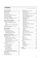
Power management 25 Screen blank mode 25 Sleep (standby) mode 25 Hibernation mode 26 Lenovo G480/G485/G580/G585/G780 ........27 Specifications 27 Status indicators 29 Fn key combinations 31 FRU replacement notices 32 Screw notices 32 Removing and replacing an FRU 33 1010 Battery pack 34 - Lenovo G585 | Hardware Maintenance Manual - Page 4
About this manual This manual contains service and reference information for the following Lenovo product: Lenovo G480/G485/G580/G585/G780 Use this manual to troubleshoot problems. The manual is divided into the following sections: • The common sections provide general information, guidelines, and - Lenovo G585 | Hardware Maintenance Manual - Page 5
the following safety information that you need to get familiar with before you service a Lenovo computer: • "General safety" on page 2 • "Electrical safety" on page 3 • "Safety inspection guide" on page 5 • "Handling devices that are sensitive to electrostatic discharge" on page 6 • "Grounding - Lenovo G585 | Hardware Maintenance Manual - Page 6
, drilling, soldering, cutting wire, attaching springs, using solvents, or working in any other conditions that may be hazardous to your eyes. • After service, reinstall all safety shields, guards, labels, and ground wires. Replace any safety device that is worn or defective. • Reinstall all covers - Lenovo G585 | Hardware Maintenance Manual - Page 7
- Working near power supplies - Removing or installing main units • Before you start to work on the you may prevent a current from passing through your body. - When using testers, set the controls correctly safety precautions when you work with very high voltages; instructions for these precautions - Lenovo G585 | Hardware Maintenance Manual - Page 8
Lenovo G480/G485/G580/G585/G780 Hardware Maintenance Manual • Always look carefully for possible hazards in your work area. Examples of conductive; such touching can cause personal injury and machine damage. • Do not service the following parts with the power on when they are removed from their - Lenovo G585 | Hardware Maintenance Manual - Page 9
service personnel from injury. This guide addresses only those items. You should use good judgment to identify potential safety hazards due to attachment of non-Lenovo features or options not covered by this inspection guide , broken, or sharp edges). 2. Turn off the computer. Disconnect the power - Lenovo G585 | Hardware Maintenance Manual - Page 10
that meets the specific service requirement. Notes: The use of a grounding system to guard against ESD damage is desirable but not necessary. - Attach the ESD ground clip to any frame ground, ground braid, or greenwire ground. - When working on a double-insulated or battery-operated system, use - Lenovo G585 | Hardware Maintenance Manual - Page 11
this section are provided in English, French, German, Hebrew, Italian, Japanese, and Spanish. Safety notice 1 Before the computer is powered on after FRU replacement, make sure all screws, springs, and other small parts are in place and are not left loose inside the computer. Verify this by shaking - Lenovo G585 | Hardware Maintenance Manual - Page 12
Lenovo G480/G485/G580/G585/G780 Hardware Maintenance Manual Safety notice 2 DANGER Some standby batteries contain a small amount of nickel and cadmium. Do not disassemble a standby battery, recharge it, throw it into fire or water, or short-circuit it. Dispose of the battery as required by local - Lenovo G585 | Hardware Maintenance Manual - Page 13
pack as required by local ordinances or regulations. Use only the battery in the appropriate parts listing when replacing the battery pack. Use of an incorrect battery can result in ignition or explosion of the battery. La batterie contient du nickel. Ne la démontez pas, ne l'exposez ni au feu - Lenovo G585 | Hardware Maintenance Manual - Page 14
Lenovo G480/G485/G580/G585/G780 Hardware Maintenance Manual Safety notice 4 DANGER The lithium battery can cause a fire, an explosion, or a severe burn. Do not recharge it, remove its polarized connector, el contenido de sus celdas al agua. Deséchela tal como dispone la normativa local. 10 - Lenovo G585 | Hardware Maintenance Manual - Page 15
Safety information Safety notice 5 If the LCD breaks and the fluid from inside the LCD gets into your eyes or on your hands, immediately wash the affected areas with water at least for 15 minutes. Seek medical care if any symptoms caused by the fluid are present after washing. Si le panneau d' - Lenovo G585 | Hardware Maintenance Manual - Page 16
Lenovo G480/G485/G580/G585/G780 Hardware Maintenance Manual Safety notice 6 DANGER To avoid shock, do not remove the um brennbare Materialien zu entzünden oder Verletzungen bei Personen hervorzurufen. Sebbene le batterie di alimentazione siano a basso voltaggio, una batteria in corto circuito o a - Lenovo G585 | Hardware Maintenance Manual - Page 17
Safety information Safety notice 8 DANGER Before removing any FRU, turn off the computer, unplug all power cords from electrical outlets, remove the battery pack, and then disconnect any interconnecting cables. Avant de retirer une unité remplaçable en clientèle, mettez le système hors tension, dé - Lenovo G585 | Hardware Maintenance Manual - Page 18
G580/G585/G780 Hardware Maintenance Manual Laser compliance statement Some models of Lenovo conform to the requirements of the Department of Health and Human Services 21 Code of Federal Regulations (DHHS 21 CFR) Subchapter di procedure diverse da quelle specificate possono provocare l'esposizione a. - Lenovo G585 | Hardware Maintenance Manual - Page 19
Safety information A CD-ROM drive, a DVD-ROM drive, or any other storage device installed may contain an embedded Class 3A or Class 3B laser diode. Note the following: DANGER Emits visible and invisible laser radiation when open. Do not stare into the beam, do not view directly with optical - Lenovo G585 | Hardware Maintenance Manual - Page 20
BIOS and device drivers are posted on the customer support site: http://consumersupport.lenovo.com/. Strategy for replacing FRUs Before replacing parts: Make sure that all software fixes, drivers, and BIOS downloads are installed before replacing any FRUs listed in this manual. After a system board - Lenovo G585 | Hardware Maintenance Manual - Page 21
information Use the following strategy to prevent unnecessary expense for replacing and servicing FRUs: • If you are instructed to replace an FRU, but the replacement does not solve the problem, reinstall the original FRU before you continue. • Some computers have both a processor board and a system - Lenovo G585 | Hardware Maintenance Manual - Page 22
Lenovo G480/G485/G580/G585/G780 Hardware Maintenance Manual Important information about replacing RoHS compliant FRUs RoHS, The Restriction its suppliers to be ready to support Lenovo's requirements and schedule in the EU. Products sold in 2005 and 2006 will contain some RoHS compliant FRUs. The - Lenovo G585 | Hardware Maintenance Manual - Page 23
can service the computer. • Before replacing any FRU, read the entire page on removing and replacing FRUs. • When you replace FRUs as cosmic radiation, electrostatic discharge, or software errors. Consider replacing an FRU only when a problem recurs. If you suspect that an FRU is defective, clear - Lenovo G585 | Hardware Maintenance Manual - Page 24
the computer unusable) • Sticky keys caused by spilling a liquid onto the keyboard • Use of an incorrect AC adapter on laptop products The following symptoms might indicate damage caused by nonwarranted activities: • Missing parts might be a symptom of unauthorized service or modification. • If the - Lenovo G585 | Hardware Maintenance Manual - Page 25
adapter pin No. 2 may differ from the one you are servicing. 3. If the voltage is not correct, replace the AC adapter. 4. If the voltage is acceptable, do the following: • Replace the system board. • If the problem persists, go to "Lenovo G480/G485/G580/G585/G780" on page 27. Note: Noise from the AC - Lenovo G585 | Hardware Maintenance Manual - Page 26
Lenovo G480/G485/G580/G585/G780 Hardware Maintenance Manual Checking operational charging To check whether the battery charges properly during operation, use a discharged battery pack or a battery pack that has less than 50% of the total power remaining when installed in the computer. Perform - Lenovo G585 | Hardware Maintenance Manual - Page 27
into the optical drive. 2. Start the computer. When the Lenovo logo comes up, immediately press F12; on the boot sequence menu, select the optical drive as the first boot-up device. The computer will boot from the Start Recovery Disc. Follow the on-screen instructions to begin the recovery process - Lenovo G585 | Hardware Maintenance Manual - Page 28
Windows screen is displayed. Follow the instructions on the screen to complete the Windows setup. Passwords As many as three passwords may be needed for any Lenovo to the servicer, there is no service procedure to reset the password. The system board must be replaced for a scheduled fee. 24 - Lenovo G585 | Hardware Maintenance Manual - Page 29
Related service information Power management Note: Power management modes are not supported for APM operating system. To reduce power consumption, the computer has three power management modes: screen blank, sleep (standby), and hibernation. Screen blank mode If the time set on the "Turn off monitor - Lenovo G585 | Hardware Maintenance Manual - Page 30
Lenovo G480/G485/G580/G585/G780 Hardware Maintenance Manual Hibernation mode In hibernation mode, the following occurs: • The system status, RAM, VRAM, and setup data are stored on the hard disk. • The system is powered off. To cause the computer to enter hibernation mode, follow the steps below: • - Lenovo G585 | Hardware Maintenance Manual - Page 31
G480/G485/G580/G585/G780 Lenovo G480/G485/G580/G585/G780 This chapter presents the following product-specific service references and product-specific parts information: • "Specifications" on page 27 • "Status indicators" on page 29 • "Fn key combinations" on page 31 • "FRU replacement notices" on - Lenovo G585 | Hardware Maintenance Manual - Page 32
/G580/G585) • Built-in stereo speakers • Built-in microphone Video • CRT port x 1, HDMI port x 1 Ethernet (on the system board) • 10/100 M or 10/100/1000 M Ethernet PCI Express Mini Card slot • 1 slot for WLAN card (half size) Bluetooth wireless • option Keyboard • 6 Row, Lenovo Keyboard - Lenovo G585 | Hardware Maintenance Manual - Page 33
/G580/G585 Lenovo G780 3 4 1 1 2 G770 3 4 5 6 Table 2. Status indicators Indicator Meaning a Caps lock b Num lock c Power on White: Caps Lock mode is enabled. You can enter all alphabetic characters (A-Z) in uppercase without pressing the Shift key. To enable or disable Caps Lock mode - Lenovo G585 | Hardware Maintenance Manual - Page 34
Lenovo G480/G485/G580/G585/G780 Hardware Maintenance Manual d Battery status Blinking amber: (500ms off/1s on) The remaining power of the battery is less than 5% of its capacity. Blinking amber: (100ms off/3.2s on) The battery put the computer into standby mode or turn off the computer. Note:Do - Lenovo G585 | Hardware Maintenance Manual - Page 35
of Fn with a function key. Table 3. Fn key combinations Key combination Description Fn + Esc: Turn on/off the integrated camera. Fn + F1: Enter sleep mode. Fn + F2: Turn on/off the backlight of the LCD screen. Fn + F3: Open the interface for the display device switch to select this - Lenovo G585 | Hardware Maintenance Manual - Page 36
/G485/G580/G585/G780 Hardware Maintenance Manual FRU replacement notices This section presents notices related to removing and replacing parts. Read this section carefully before replacing any FRU. Screw notices Loose screws can cause a reliability problem. In the Lenovo computer, this problem is - Lenovo G585 | Hardware Maintenance Manual - Page 37
Lenovo G480/G485/G580/G585/G780 Removing and replacing an FRU This section presents exploded figures with the instructions to indicate how to remove and replace the FRU. Make sure to observe the following general rules: 1. Do not attempt to service any computer unless you have been trained and - Lenovo G585 | Hardware Maintenance Manual - Page 38
or explode. Figure 1. Removal steps of battery pack Unlock the manual battery latch a. Holding the spring-loaded battery latch in the unlocked position b, remove the battery pack in the direction shown by the arrow c. Lenovo G480/G485/G580/G585 1 3 Lenovo G780 1 2 2 3 When installing: Install the - Lenovo G585 | Hardware Maintenance Manual - Page 39
Lenovo G480/G485/G580/G585/G780 1020 Dummy card For access, remove this FRU: • "1010 Battery pack" on page 34 Figure 2. Removal steps of dummy card Remove the dummy card in the direction shown by arrows a b . Lenovo G480/G485/G580/G585 1 2 Lenovo G780 1 2 35 - Lenovo G585 | Hardware Maintenance Manual - Page 40
Lenovo G480/G485/G580/G585/G780 Hardware Maintenance Manual 1030 Optical drive/Hard disk drive (HDD)/Memory/Central processing unit/Mini PCI Express Card slot compartment cover For access, remove this FRU: • "1010 Battery pack" on page 34 Figure 3. Removal steps of Optical drive/Hard disk drive (HDD - Lenovo G585 | Hardware Maintenance Manual - Page 41
G480/G485/G580/G585/G780 Lenovo G780: Loosen the four screws a and remove the two screws b , then remove the compartment cover in the direction shown by the arrow c. 2 1 3 2 1 1 Step a b Screw (quantity) G480: M2.5×8.0 mm, flat-head, nylok-coated (2) G580: M2.5×4.0 mm, flat-head, nylok-coated - Lenovo G585 | Hardware Maintenance Manual - Page 42
Lenovo G480/G485/G580/G585/G780 Hardware Maintenance Manual Note: Applying labels to the base cover The new base cover FRU is shipped with a kit containing labels of several kinds. When you replace the base cover, you need to apply the following label: The following labels need to be peeled off from - Lenovo G585 | Hardware Maintenance Manual - Page 43
Lenovo G480/G485/G580/G585/G780 1040 Hard disk drive For access, remove these FRUs in order: • "1010 Battery pack" on page 34 • "1030 Optical drive/Hard disk drive (HDD)/Memory or is in suspend mode. Figure 4. Removal steps of hard disk drive Remove the two screws a. Lenovo G480/G485/G580/G585 1 1 39 - Lenovo G585 | Hardware Maintenance Manual - Page 44
Lenovo G480/G485/G580/G585/G780 Hardware Maintenance Manual Lenovo G780 1 1 Step a Screw (quantity) M2.5×4.0 mm, flat-head, nylok-coated (2) Color Black Torque 2.0-2.5 kgfcm 40 - Lenovo G585 | Hardware Maintenance Manual - Page 45
Lenovo G480/G485/G580/G585/G780 Figure 4. Removal steps of hard disk drive (continued) Then pull the hard disk drive bracket in the direction shown by arrow b. Lenovo G480/G485/G580/G585 2 Lenovo G780 2 Remove the hard disk drive (secured in the metal frame) in the direction shown by arrow c. Lenovo - Lenovo G585 | Hardware Maintenance Manual - Page 46
Lenovo G480/G485/G580/G585/G780 Hardware Maintenance Manual Lenovo G780 3 When installing: Make sure that the hard disk drive connector is attached firmly. 42 - Lenovo G585 | Hardware Maintenance Manual - Page 47
remove this FRU: • "1010 Battery pack" on page 34 • "1030 Optical drive/Hard disk drive (HDD)/Memory/Central processing unit/Mini PCI Express Card slot compartment cover" on page 36 Figure 5. Removal steps of optical drive Remove the screw a. Lenovo G480/G485/G580/G585 1 Lenovo G780 1 Step a Screw - Lenovo G585 | Hardware Maintenance Manual - Page 48
Lenovo G480/G485/G580/G585/G780 Hardware Maintenance Manual Insert a screwdriver into the screw hole and push the optical drive in the direction shown by arrow b. Pull the optical drive out in the direction shown by arrow c. Lenovo G480/G485/G580/G585 2 3 Lenovo G780 2 3 44 - Lenovo G585 | Hardware Maintenance Manual - Page 49
Lenovo G480/G485/G580/G585/G780 1060 DIMM For access, remove these FRUs in order: • "1010 Battery pack" on page 34 • "1030 Optical drive/Hard disk drive (HDD)/Memory/Central processing unit/Mini PCI Express Card slot compartment cover" on page 36 Figure 6. Removal steps of DIMM Release the two - Lenovo G585 | Hardware Maintenance Manual - Page 50
G480/G485/G580/G585/G780 Hardware Maintenance Manual Lenovo G780 2 1 1 Note: If only one DIMM is used on the computer you are servicing, the card must be installed in SLOT-0 ( : lower slot), but not in SLOT-1 ( : upper slot). b a When installing: Insert the notched end of the DIMM into - Lenovo G585 | Hardware Maintenance Manual - Page 51
Lenovo G480/G485/G580/G585/G780 1070 PCI Express Mini Card for wireless LAN/WAN For access, remove these FRUs in order: • "1010 Battery pack" on page 34 • "1030 Optical drive/Hard disk drive (HDD)/Memory/Central processing unit/Mini PCI Express Card slot compartment cover" on page 36 Figure 7. - Lenovo G585 | Hardware Maintenance Manual - Page 52
Lenovo G480/G485/G580/G585/G780 Hardware Maintenance Manual Figure 7. Removal steps of PCI Express Mini Card for wireless LAN/WAN (continued) Remove the card in the direction shown by arrow c . 3 When installing: • In - Lenovo G585 | Hardware Maintenance Manual - Page 53
Lenovo G480/G485/G580/G585/G780 1080 Keyboard For access, remove this FRU: • "1010 Battery pack" on page 34 • "1030 Optical drive/Hard disk drive (HDD)/Memory/Central processing unit/Mini PCI Express Card slot compartment cover" on page 36 Figure 8. Removal steps of keyboard Lenovo G480/G485/G580/ - Lenovo G585 | Hardware Maintenance Manual - Page 54
Lenovo G480/G485/G580/G585/G780 Hardware Maintenance Manual Figure 8. Removal steps of keyboard (continued) Loosen the keyboard with fingers in the direction shown by arrow b. Lenovo G480/G485/G580/G585 2 Lenovo G780 G770 2 50 - Lenovo G585 | Hardware Maintenance Manual - Page 55
G480/G485/G580/G585/G780 Figure 8. Removal steps of keyboard (continued) Lift the keyboard a little c, and then detach the connector in the direction shown by arrows d e . Lenovo G480/G485/G580/G585 3 4 5 Lenovo G780 3 G770 4 5 When installing: Make sure that the FPC connector is attached firmly - Lenovo G585 | Hardware Maintenance Manual - Page 56
Lenovo G480/G485/G580/G585/G780 Hardware Maintenance Manual 1090 Keyboard bezel For access, remove these FRUs in order: • "1010 Battery pack" on page 34 • "1030 Optical drive/Hard disk drive (HDD)/Memory/Central processing unit/Mini PCI Express Card slot compartment cover" on page 36 • "1040 Hard - Lenovo G585 | Hardware Maintenance Manual - Page 57
G480/G485/G580/G585/G780 Lenovo G780 Remove the sixteen screws a, the four screws b and the two screws c on the bottom. 1 3 3 1 1 1 1 2 1 2 2 1 2 1 1 1 1 1 Step a b c Screw (quantity) Color G480/G485/G580/G585: M2.5×6.0 mm, flat-head, nylok-coated (11) G780: M2.5×8.0 mm, flat-head - Lenovo G585 | Hardware Maintenance Manual - Page 58
G585/G780 Hardware Maintenance Manual Figure 9. Removal steps of keyboard bezel (continued) Lenovo G480/G485/G580/G585 Remove the screw d . 4 Lenovo G780 Remove the four screws d . 4 G770 4 4 4 Step d Screw (quantity) Color G480/G485/G580/G585: M2.5×6.0 mm, flat-head, nylok-coated (1) G780 - Lenovo G585 | Hardware Maintenance Manual - Page 59
Lenovo G480/G485/G580/G585/G780 Figure 9. Removal steps of keyboard bezel (continued) Detach the FPC connectors in the direction shown by arrows e . Lenovo G480/G485/G580/G585 5 5 Lenovo G780 5 5 G770 5 55 - Lenovo G585 | Hardware Maintenance Manual - Page 60
/G585/G780 Hardware Maintenance Manual Figure 9. Removal steps of keyboard bezel (continued) Remove the keyboard bezel in the direction shown by arrow f . Lenovo G480/G485/G580/G585 6 Lenovo G780 G770 6 When installing: Make sure that all the FPC connectors, microphone connectors are attached firmly - Lenovo G585 | Hardware Maintenance Manual - Page 61
Lenovo G480/G485/G580/G585/G780 Figure 9. Removal steps of keyboard bezel (continued) Remove the two screws g, and then remove the power board in the direction shown by arrow h. Lenovo G480/G485/G580/G585 7 7 8 Lenovo G780 7 7 8 57 - Lenovo G585 | Hardware Maintenance Manual - Page 62
G480/G485/G580/G585/G780 Hardware Maintenance Manual Lenovo G780 Remove the screw i, and then remove the power board in the directioshown by arrow j h. 9 10 Step g i Screw (quantity) M2.0×3.0 mm, flat-head, nylok-coated (2) G780: M2.0×3.0 mm, flat-head, nylok-coated (1) Color Black Black Torque - Lenovo G585 | Hardware Maintenance Manual - Page 63
Lenovo G480/G485/G580/G585) For access, remove these FRUs in order: • "1010 Battery pack" on page 34 • "1020 Dummy card" on page 35 • "1030 Optical drive/Hard disk drive (HDD)/Memory Keyboard" on page 49 • "1090 Keyboard bezel" on page 52 Figure 10. Removal steps of speakers (Lenovo G480/G485/G580/ - Lenovo G585 | Hardware Maintenance Manual - Page 64
Lenovo G480/G485/G580/G585/G780 Hardware Maintenance Manual "1010 Battery pack" on page 34 • "1020 Dummy card" on page 35 • "1030 Optical drive/Hard disk drive (HDD)/Memory/Central Keyboard" on page 49 • "1090 Keyboard bezel" on page 52 • "1100 Speakers (Lenovo G480/G485/G580/G585)" on page 59 60 - Lenovo G585 | Hardware Maintenance Manual - Page 65
Lenovo G480/G485/G580/G585/G780 Figure 11. Removal steps of system board Lenovo G480/G485/G580/G585 Remove the three screws a. Unplug the LCD and Bluetooth connectors in the direction shown by arrows b. Detach the two FPC connectors in the direction shown by arrows c. 2 1 1 2 1 3 3 61 - Lenovo G585 | Hardware Maintenance Manual - Page 66
G480/G485/G580/G585/G780 Hardware Maintenance Manual Lift the system board a little d, and then detach the power connector in the direction shown by arrow e. 5 6 Lenovo G780 Remove the three screws a. Unplug the speakers and the bluetooth connectors in the direction shown by arrows b. Detach the - Lenovo G585 | Hardware Maintenance Manual - Page 67
Lenovo G480/G485/G580/G585/G780 Remove two screws d. Unplug the LCD connector and power jack connector in the direction shown by arrows e f. 6 4 4 5 Step a d Screw (quantity) M2.5×4.0 mm, flat- - Lenovo G585 | Hardware Maintenance Manual - Page 68
Lenovo G480/G485/G580/G585/G780 Hardware Maintenance Manual Figure 11. Removal steps of system board (continued) Remove the system board in the direction shown by arrow g. Lenovo G480/G485/G580/G585 7 Lenovo G780 G770 7 64 - Lenovo G585 | Hardware Maintenance Manual - Page 69
Lenovo G480/G485/G580/G585/G780 Figure 11. Removal steps of system board (continued) Remove the screw h. Then remove the card reader board in the direction shown by arrow i. Lenovo G480/G485/G580/G585 8 9 a a 65 - Lenovo G585 | Hardware Maintenance Manual - Page 70
G480/G485/G580/G585/G780 Hardware Maintenance Manual Figure 11. Removal steps of system board (continued) Lenovo G780 G770 9 8 aa Step h Screw (quantity) M2.5×4.0 mm, flat-head, nylok-coated (1) Color Black Torque 2.0-2.5 kgfcm When installing: When installing: When attaching the system - Lenovo G585 | Hardware Maintenance Manual - Page 71
Remove the screws j. Then remove the card reader board in the direction shown by arrow k. Lenovo G480/G485/G580/G585 10 10 11 Lenovo G780 G770 10 11 Step j Screw (quantity) Color G480/G485/G580/G585: M2.5×4.0 mm, flat-head, nylok-coated (2) G780: M2.5×4.0 mm, flat-head, nylok-coated (1) Black - Lenovo G585 | Hardware Maintenance Manual - Page 72
G480/G485/G580/G585/G780 Hardware Maintenance Manual Figure 11. Removal steps of system board (continued) Lenovo G480/G485/G580/G585 Remove the screw l j. Then remove the USB board in the direction shown by arrow m j. 12 13 Step l Screw (quantity) G480/G485/G580/G585: M2.5×4.0 mm, flat-head - Lenovo G585 | Hardware Maintenance Manual - Page 73
Lenovo G480/G485/G580/G585/G780 Figure 11. Removal steps of system board (continued) Lenovo G780 G770 14 When installing: Make sure that all the connectors are attached firmly. 69 - Lenovo G585 | Hardware Maintenance Manual - Page 74
Lenovo G480/G485/G580/G585/G780 Hardware Maintenance Manual 1120 LCD unit For access, remove these FRUs in order: • "1010 Battery pack" on page 34 • "1020 Dummy card" on page 35 • "1030 Optical drive/Hard disk drive (HDD)/Memory/Central processing unit/Mini PCI Express Card slot compartment cover" - Lenovo G585 | Hardware Maintenance Manual - Page 75
/G780 Figure 12. Removal steps of LCD unit (continued) Lenovo G480/G485/G580/G585 33 33 2 2 2 Lenovo G780 3 3 G770 2 2 3 3 Step c Screw (quantity) Color G480/G485/G580/G585: M2.5×6.0 mm, flat-head, nylok-coated (4) G780: M2.5×5.0 mm, flat-head, nylok-coated (4) Black white Torque - Lenovo G585 | Hardware Maintenance Manual - Page 76
Lenovo G480/G485/G580/G585/G780 Hardware Maintenance Manual When installing: • Route the antenna cables along the cable guides. As you route the cables, make sure that they are not subjected to any tension. Tension could cause the cables to be damaged by the cable guides, or a wire to be broken. • - Lenovo G585 | Hardware Maintenance Manual - Page 77
Lenovo G780 Lenovo G480/G485/G580/G585/G780 4 4 73 - Lenovo G585 | Hardware Maintenance Manual - Page 78
Lenovo G480/G485/G580/G585/G780 Hardware Maintenance Manual 1130 Fan assembly and Heat Sink assembly For access, remove these FRUs in order: • "1010 Battery pack" on page 34 • "1020 Dummy card" on page 35 • "1030 Optical drive/Hard disk drive (HDD)/Memory/Central processing unit/Mini PCI Express - Lenovo G585 | Hardware Maintenance Manual - Page 79
/G780 Figure 13. Removal steps of fan assembly and heat sink assembly (continued) Lenovo G480/G485/G580/G585 Remove the three screws b and the four screws c. 2 2 2 3 3 3 Lenovo G780 Remove the three screws b a and the one screw c. 2 2 2 3 Step b c Screw (quantity) Color M2.0×3.2 mm - Lenovo G585 | Hardware Maintenance Manual - Page 80
G480/G485/G580/G585/G780 Hardware Maintenance Manual Figure 13. Removal steps of fan assembly and heat sink assembly (continued) Lift the fan assembly and heat sink assembly in the direction shown by arrow d. Lenovo G480/G485/G580/G585 4 Lenovo G780 4 Note: Be careful not to damage the connector - Lenovo G585 | Hardware Maintenance Manual - Page 81
/G580/G585/G780 Lenovo G480/G485/G580/G585 b a Lenovo G780 a When installing: Before you attach the fan assembly to the computer, apply thermal grease, at an amount of 0.2 grams, to the part shown in the figure above. Either too much or too less grease application can cause a thermal problem - Lenovo G585 | Hardware Maintenance Manual - Page 82
Lenovo G480/G485/G580/G585/G780 Hardware Maintenance Manual 1140 CPU For access, remove these FRUs in order: • "1010 Battery pack" on page 34 • "1020 Dummy card" on page 35 • "1030 Optical drive/Hard disk drive (HDD)/Memory/Central processing unit/Mini PCI Express Card slot compartment cover" on - Lenovo G585 | Hardware Maintenance Manual - Page 83
Lenovo G780 Lenovo G480/G485/G580/G585/G780 1 a b 2 When installing: Place the CPU on the CPU socket in the direction shown by arrow , and then rotate the head of the screw in the direction shown by arrow to secure the CPU. 79 - Lenovo G585 | Hardware Maintenance Manual - Page 84
Lenovo G480/G485/G580/G585/G780 Hardware Maintenance Manual 1150 Base cover For access, remove these FRUs in order: • "1010 Battery pack" on page 34 • "1020 Dummy card" on page 35 • "1030 Optical drive/Hard disk drive (HDD)/Memory/Central processing unit/Mini PCI Express Card slot compartment cover" - Lenovo G585 | Hardware Maintenance Manual - Page 85
Lenovo G480/G485/G580/G585/G780 Figure 15. Removal steps of base cover (continued) Lenovo G780 Remove the four screws b. Then remove the speakers by lifting in the direction shown by arrows c. 2 2 3 2 2 3 Step b Screw (quantity) M2.0×5.7+2 mm, flat-head, nylok- - Lenovo G585 | Hardware Maintenance Manual - Page 86
Lenovo G480/G485/G580/G585/G780 Hardware Maintenance Manual 1160 LCD front bezel For access, remove these FRUs in order: • "1010 Battery pack" on page 34 • "1020 Dummy card" on page 35 • "1030 Optical drive/Hard disk drive (HDD)/Memory/Central processing unit/Mini PCI Express Card slot compartment - Lenovo G585 | Hardware Maintenance Manual - Page 87
Lenovo G780 1 Lenovo G480/G485/G580/G585/G780 1 Step a Screw (quantity) G480/G485/G580/G585: M2.5×6.0 mm, flat-head, nylok-coated (2) G780: M2.5×5.0 mm, flat-head, nylok-coated (2) Color White Black Torque 2.0-2.5 kgfcm 2.0-2.5 kgfcm 83 - Lenovo G585 | Hardware Maintenance Manual - Page 88
Lenovo G480/G485/G580/G585/G780 Hardware Maintenance Manual Figure 16. Removal steps of LCD front bezel (continued) Remove the LCD front bezel in the direction shown by arrows b. Lenovo G480/G485/G580/G585 2 2 2 2 Lenovo G780 2 2 2 2 84 - Lenovo G585 | Hardware Maintenance Manual - Page 89
Lenovo G480/G485/G580/G585/G780 1170 LCD panel, LCD cable and hinges For access, remove these FRUs in order: • "1010 Battery pack" on page 34 • "1020 Dummy card" on page 35 • "1030 Optical drive/Hard disk drive (HDD)/Memory/Central processing unit/Mini PCI Express Card slot compartment cover" on - Lenovo G585 | Hardware Maintenance Manual - Page 90
Lenovo G480/G485/G580/G585/G780 Hardware Maintenance Manual Lenovo G780 1 1 3 2 1 1 3 3 Step a Screw (quantity) M2.5×4.0 mm, flat-head, nylok-coated (4) Color Black Torque 2.0-2.5 kgfcm 86 - Lenovo G585 | Hardware Maintenance Manual - Page 91
(continued) Remove the eight screws d, release the hinges from the LCD panel in the direction shown by arrows e. Lenovo G480/G485/G580/G585 5 4 4 4 4 Lenovo G780 5 4 4 4 4 4 4 4 4 5 Step d Screw (quantity) M2.0×3.0 mm, flat-head, nylok-coated (8) 4 4 4 4 5 Color Black Torque 1.5-2.0 kgfcm 87 - Lenovo G585 | Hardware Maintenance Manual - Page 92
Hardware Maintenance Manual Figure 17. Removal steps of LCD panel, LCD cable and hinges (continued) Note: The LCD cables are attached to the LCD panel by a metal connector. Peel off the adhesive tape and detach the connector in the direction shown by arrow f. Lenovo G480/G485/G580/G585 6 Lenovo G780 - Lenovo G585 | Hardware Maintenance Manual - Page 93
Lenovo G480/G485/G580/G585/G780 1180 Integrated camera For access, remove these FRUs in order: • "1010 Battery pack" on page 34 • "1020 Dummy card" on page 35 • "1030 Optical drive/Hard disk drive (HDD)/Memory/Central processing unit/Mini PCI Express Card slot compartment cover" on page 36 • "1040 - Lenovo G585 | Hardware Maintenance Manual - Page 94
Lenovo G480/G485/G580/G585/G780 Hardware Maintenance Manual Lenovo G780 1 When installing: Stick the integrated camera to the top center of the LCD cover and ajust the placement of it to make sure the connector is attached firmly. 90 - Lenovo G585 | Hardware Maintenance Manual - Page 95
Lenovo G480/G485/G580/G585/G780 1190 Antenna assembly and LCD cover For access, remove these FRUs in order: • "1010 Battery pack" on page 34 • "1020 Dummy card" on page 35 • "1030 Optical drive/Hard disk drive (HDD)/Memory/Central processing unit/Mini PCI Express Card slot compartment cover" on page - Lenovo G585 | Hardware Maintenance Manual - Page 96
module antennas may be placed in different positions (2a/2b) depending on different configurations. c Computer display d OneKey Rescue System button e Power button f Built-in microphone g System status indicators h Touchpad i Memory card slot Lenovo G480/G485/G580/G585 2 1 3 2 4 5 6 7 8 9 92 - Lenovo G585 | Hardware Maintenance Manual - Page 97
Lenovo G780 Lenovo G480/G485/G580/G585/G780 2 1 2 3 7 4 5 G770 6 8 7 9 93 - Lenovo G585 | Hardware Maintenance Manual - Page 98
Lenovo G480/G485/G580/G585/G780 Hardware Maintenance Manual Right-side view a Combo audio jack b Optical drive c USB port d AC power adapter jack e Headphone jack d f Microphone jack Lenovo G480/G485/G580/G585 Lenovo G780 4 3 2 1 4 23 2 6 5 94 - Lenovo G585 | Hardware Maintenance Manual - Page 99
) c RJ-45 port d VGA port e Fan louvers f Kensington slot g Optical drive/Hard disk drive (HDD)/Memory/CPU (Central processing unit)/Mini PCI Express Card slot compartment h Battery latch - spring loaded i Battery pack j Battery latch - manual k Speaker Lenovo G480/G485/G580/G585 10 9 8 7 11 11 - Lenovo G585 | Hardware Maintenance Manual - Page 100
Lenovo G480/G485/G580/G585/G780 Hardware Maintenance Manual Lenovo G780 10 9 8 6 5 11 4 3 2 7 11 1 1 1 96 - Lenovo G585 | Hardware Maintenance Manual - Page 101
Lenovo G480/G485/G580/G585/G780 Parts list This section presents the following service parts: • "Overall" on page 98 • "LCD FRUs" on page 105 • "Keyboard" on page 108 • "Miscellaneous parts" on page 114 • "AC adapters" on page 115 • "Power cords" on page 116 Notes: • Each FRU is available for all - Lenovo G585 | Hardware Maintenance Manual - Page 102
Lenovo G480/G485/G580/G585/G780 Hardware Maintenance Manual Overall Lenovo G480/G485/G580/G585 1 2 a e 3 4 5 f 6 g 10 7 11 8 12 9 h 13 14 15 16 17 18 19 b 20 d c 21 22 98 - Lenovo G585 | Hardware Maintenance Manual - Page 103
Lenovo G780 2 Lenovo G480/G485/G580/G585/G780 1 3 4 6 e 7 10 f 11 8 g 12 9 13 14 h 16 15 17 18 d 19 22 b 20 c 21 99 - Lenovo G585 | Hardware Maintenance Manual - Page 104
Lenovo G480/G485/G580/G585/G780 Hardware Maintenance Manual 100 Table 4. Parts list-Overall No. FRU 1 LCD unit (see "LCD FRUs" on page 105.) 2 Keyboard (see "Keyboard" on page 108.) 3 QIWG5 Power Board UMA W/Cable (G480/G485) 3 QIWG5 Power Board DIS W/Cable (G480/G485) 3 LG48 Power Board W/Cable ( - Lenovo G585 | Hardware Maintenance Manual - Page 105
Lenovo G480/G485/G580/G585/G780 Table 4. Parts list-Overall (continued) No. FRU FRU no. 9 QIWG6 IO Board W/Cable 455M0X38L41 (G580/G585) 90200454 9 CARD READER 5 IN 1-17 (G780) 31050105 10 LG48 TouchPad Button Poard (G480) 90000302 10 LG58 TouchPad Button Board (G580) 90000307 10 QIWG6 - Lenovo G585 | Hardware Maintenance Manual - Page 106
Lenovo G480/G485/G580/G585/G780 Hardware Maintenance Manual Table 4. Parts list-Overall (continued) No. battery Comm02 17 Battery, 6cell 4400mAh 48Wh, Sanyo L11S6Y01 3S2P 48Wh 121500040 battery Comm02 17 Battery, 6cell 4400mAh 48Wh, LG L11L6Y01 3S2P 48Wh battery 121500042 Comm02 17 Battery - Lenovo G585 | Hardware Maintenance Manual - Page 107
Lenovo G480/G485/G580/G585/G780 Table 4. Parts list-Overall (continued) No. FRU FRU no. 19 HDD, 500G 5400rpm, WD (ML375M), WD WD5000BPVT-24HXZ 16004846 5400RPM 19 HDD, 500G - Lenovo G585 | Hardware Maintenance Manual - Page 108
Lenovo G480/G485/G580/G585/G780 Hardware Maintenance Manual Table 5. Parts list-Overall (continued) No. FRU 21 QIWG5 SD Dummy Card FA0N1000F00 21 LG48 SD Dummy Card (G480) 21 LG58 SD Dummy (G580) 21 SD 5IN1 DUMMY CARD (G780) 21 SD 2IN1 DUMMY CARD (G780) 22 QIWG5 Thermal Door AP0N1000200 (G480/G485) - Lenovo G585 | Hardware Maintenance Manual - Page 109
Lenovo G480/G485/G580/G585/G780 LCD FRUs In Lenovo G480/G485/G580/G585/G780, there are following types of LCDs. • "14.0-in. HD TFT" (G480/G485) • "15.6-in. HD TFT" (G580/G585) • "17.3-in. HD TFT" (G780) i 1 2 3 4 5 6 7 105 - Lenovo G585 | Hardware Maintenance Manual - Page 110
Lenovo G480/G485/G580/G585/G780 Hardware Maintenance Manual 14.0-in. HD TFT Table 5. Parts list-14.0-in. HD TFT No. FRU FRU no. 1 QIWG5 LCD Bezel AP0N1000500 90200437 1 LG48 LCD Bezel (G480) 90200965 2 - Lenovo G585 | Hardware Maintenance Manual - Page 111
0.3M PK40000GT10/GQ10 90200445 6 QIWG6 Antenna 2 DC33000YF00/10 90200465 6 LG58 Antenna L (G580) 90200993 6 LG58 Antenna R (G580) 90200994 7 LG58 LCD Cover Brown (G580) 90200986 7 LG58 LCD Cover Red (G580) 90200984 7 LG58 LCD Cover Blue (G580) 90200985 7 QIWG6 LCD Cover MBH AP0N2000410 - Lenovo G585 | Hardware Maintenance Manual - Page 112
Lenovo G480/G485/G580/G585/G780 Hardware Maintenance Manual Keyboard Table 6. Parts list-Keyboard Language Chicony G480/G485 Sunrex English U.K. English Italian Spanish Turkish Thai Portuguese Latin Canadian English&French Korean Traditional Chinese Russian French German Arabic Brazilian Japanese - Lenovo G585 | Hardware Maintenance Manual - Page 113
Lenovo G480/G485/G580/G585/G780 Table 6. Parts list-Keyboard (continued) Language Brazilian Japanese Dutch Greek Hebrew Hungarian Sunrex (continued) Four Nordic countries Belgian Icelandic Slovenian Swiss International English Czechoslovakian Bulgarian Indic English U.K. English - Lenovo G585 | Hardware Maintenance Manual - Page 114
Lenovo G480/G485/G580/G585/G780 Hardware Maintenance Manual Table 6. Parts list-Keyboard Language Chicony G580/G585 Sunrex English U.K. English Italian Spanish Turkish Thai Portuguese Latin Canadian English&French Korean Traditional Chinese Russian French German Arabic Brazilian Japanese Dutch - Lenovo G585 | Hardware Maintenance Manual - Page 115
Lenovo G480/G485/G580/G585/G780 Table 6. Parts list-Keyboard (continued) Language German Arabic Brazilian Japanese Dutch Greek Hebrew Hungarian Sunrex (continued) Four Nordic countries Belgian Icelandic Slovenian Swiss International English Czechoslovakian Bulgarian Indic English - Lenovo G585 | Hardware Maintenance Manual - Page 116
Lenovo G480/G485/G580/G585/G780 Hardware Maintenance Manual Table 6. Parts list-Keyboard Language Chicony G780 Sunrex English U.K. English Italian Spanish Turkish Thai Portuguese Latin Canadian English&French Korean Traditional Chinese Russian French German Arabic Brazilian Japanese Dutch - Lenovo G585 | Hardware Maintenance Manual - Page 117
Lenovo G480/G485/G580/G585/G780 Table 6. Parts list-Keyboard (continued) Language Brazilian Japanese Dutch Greek Hebrew Hungarian Sunrex (continued) Four Nordic countries Belgian Icelandic Slovenian Swiss International English Czechoslovakian Bulgarian Indic English U.K. English - Lenovo G585 | Hardware Maintenance Manual - Page 118
Lenovo G480/G485/G580/G585/G780 Hardware Maintenance Manual Miscellaneous parts Table 7. Parts list-Miscellaneous parts FRU P/N System miscellaneous parts: • (a) LG48 TP Bracket (G480) • (a) LG58 TouchPad Bracket (G580) • (b) QIWG5 ODD Bracket AM0N1000500 • (b) LG48 ODD Bracket • (b) ODD - Lenovo G585 | Hardware Maintenance Manual - Page 119
Lenovo G480/G485/G580/G585/G780 AC adapters Table 8. Parts list-3-pin AC adapters FRU AC Adaptor, 65W, Delta ADP-65KH BD 20V/3.25A AC Adaptor, 65W, Liteon PA- - Lenovo G585 | Hardware Maintenance Manual - Page 120
G480/G485/G580/G585/G780 Hardware Maintenance Manual 116 Power cords A Lenovo power cord for a specific country or region is usually available only in that country or region: Table 9. Parts list-3-pin power cords Region P/N CCC • 3PIN LINETEK PC323+RVV300/300+ - Lenovo G585 | Hardware Maintenance Manual - Page 121
Lenovo G480/G485/G580/G585/G780 Table 9. Parts list-3-pin power cords (continued) Region Israel • 3PIN Longwell LP-41+H03VV-F+LS-18 1m UL • 3PIN Longwell LP-30B+SPT-2 - Lenovo G585 | Hardware Maintenance Manual - Page 122
Lenovo G480/G485/G580/G585/G780 Hardware Maintenance Manual Table 9. Parts list-3-pin power cords (continued) Region Argentina • 3PIN VOLEX VA2073+H03VV-F+VAC5S 1m Brazil • 3PIN VOLEX CH10S3+H03VV-F+VAC5S 1m Israel • 3PIN VOLEX - Lenovo G585 | Hardware Maintenance Manual - Page 123
may not offer the products, services, or features discussed in this document in all countries. Consult your local Lenovo representative for information on the products and services currently available in your area. Any reference to a Lenovo product, program, or service is not intended to state or - Lenovo G585 | Hardware Maintenance Manual - Page 124
Lenovo G480/G485/G580/G585/G780 Hardware Maintenance Manual Any Windows® Windows® 7 The following are trademarks of Intel Corporation or its subsidiaries in the United States, other countries, or both: Intel® Intel®Core™ 2 Duo Other company, product, or service names may be the trademarks or service
-
 1
1 -
 2
2 -
 3
3 -
 4
4 -
 5
5 -
 6
6 -
 7
7 -
8
-
9
-
10
-
11
-
12
-
13
-
14
-
15
-
16
-
17
-
18
-
19
-
20
-
21
-
22
-
23
-
24
-
25
-
26
-
27
-
28
-
29
-
30
-
31
-
32
-
33
-
34
-
35
-
36
-
37
-
38
-
39
-
40
-
41
-
42
-
43
-
44
-
45
-
46
-
47
-
48
-
49
-
50
-
51
-
52
-
53
-
54
-
55
-
56
-
57
-
58
-
59
-
60
-
61
-
62
-
63
-
64
-
65
-
66
-
67
-
68
-
69
-
70
-
71
-
72
-
73
-
74
-
75
-
76
-
77
-
78
-
79
-
80
-
81
-
82
-
83
-
84
-
85
-
86
-
87
-
88
-
89
-
90
-
91
-
92
-
93
-
94
-
95
-
96
-
97
-
98
-
99
-
100
-
101
-
102
-
103
-
104
-
105
-
106
-
107
-
108
-
109
-
110
-
111
-
112
-
113
-
114
-
115
-
116
-
117
-
118
-
119
-
120
-
121
-
122
-
123
-
124
 |
 |
Lenovo G480/G485/
G580/G585/G780
Hardware
Maintenance
Manual