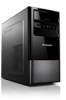
Lenovo H430 Lenovo H4 Series Hardware Replacement Guide V3.0
Lenovo H430 Manual
 |
View all Lenovo H430 manuals
Add to My Manuals
Save this manual to your list of manuals |
Lenovo H430 manual content summary:
- Lenovo H430 | Lenovo H4 Series Hardware Replacement Guide V3.0 - Page 1
Machine type: 10059/7723 10060/7724 10068/7752 10080/3099/1194 10091/2558/1196 H4 Series Hardware Replacement Guide Version 3.0 2011.08 31500379 - Lenovo H430 | Lenovo H4 Series Hardware Replacement Guide V3.0 - Page 2
Guide © Copyright Lenovo 2011. All rights reserved. LIMITED AND RESTRICTED RIGHTS NOTICE: If data or software is delivered pursuant a General Services Administration "GSA" contract, use, reproduction, or disclosure is subject to restrictions set forth in Contract No. GS-35F-05925. © 2011. Lenovo - Lenovo H430 | Lenovo H4 Series Hardware Replacement Guide V3.0 - Page 3
- Lenovo H430 | Lenovo H4 Series Hardware Replacement Guide V3.0 - Page 4
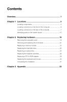
front of the computer 6 Locating connectors on the rear of the computer 7 Identifying parts on the system board 13 Chapter 2 Replacing hardware 19 Removing the computer cover 19 Removing and replacing the front bezel 21 Replacing a memory module 22 Replacing the hard disk drive 23 Replacing - Lenovo H430 | Lenovo H4 Series Hardware Replacement Guide V3.0 - Page 5
- Lenovo H430 | Lenovo H4 Series Hardware Replacement Guide V3.0 - Page 6
the TV card in this manual applies only to machines which have a TV card. It does not apply to machines which do not have a TV card. This guide contains procedures for replacing the following parts: • Memory modules • Hard disk drive • Optical drive • Graphic Card • TV Tuner • WLAN Card • Heatsink - Lenovo H430 | Lenovo H4 Series Hardware Replacement Guide V3.0 - Page 7
: • CRU removal and installation information • Publications • Troubleshooting information • Parts information • Links to other useful sources of information To access this information, go to http://consumersupport.lenovo.com. Tools required To disassemble the computer, you need the following - Lenovo H430 | Lenovo H4 Series Hardware Replacement Guide V3.0 - Page 8
and install it directly into the computer without setting the part down. When this is not possible, place the antistatic package that the part came in on a smooth, level surface and place the part on it. • Do not place the part on the computer cover or other metal surface. Hardware Replacement Guide - Lenovo H430 | Lenovo H4 Series Hardware Replacement Guide V3.0 - Page 9
4 Hardware Replacement Guide - Lenovo H430 | Lenovo H4 Series Hardware Replacement Guide V3.0 - Page 10
controls and components of the computer. To remove the computer cover, refer to "Removing the computer cover". Locating components The following illustration will help you to locate the various components in your computer. Microprocessor fan and heatsink Memory modules Hardware Replacement Guide 5 - Lenovo H430 | Lenovo H4 Series Hardware Replacement Guide V3.0 - Page 11
connectors Power supply System fan Optical drive Hard disk drive Locating connectors on the front of the computer The following illustration shows the location of connectors on the front of the computer. Power button Optical Drive (Selected models only) Memory card reader (Selected models only) USB - Lenovo H430 | Lenovo H4 Series Hardware Replacement Guide V3.0 - Page 12
location of the connectors on your computer may not be identical but should be similar to these. Please refer to the keys that follow the illustrations which identify the connectors. Lenovo H430 Voltage selection switch (Selected models only) Power connector PS/2 keyboard connector (Selected models - Lenovo H430 | Lenovo H4 Series Hardware Replacement Guide V3.0 - Page 13
-board VGA connector Ethernet connector Microphone connector Audio line-out connector Audio line-in connector Standalone graphic card (Selected models only) Expansion card slots (Access connectors for any installed PCI express cards) Lenovo H415 Voltage selection switch (Selected models only) Power - Lenovo H430 | Lenovo H4 Series Hardware Replacement Guide V3.0 - Page 14
Audio line-in connector PCI Express X 16 graphics adapter connector (Some models are equipped with a graphic card) PCI Express X 1 adapter connector (Some models are equipped with a WIFI card or TV tuner card) Lenovo H405 Voltage selection switch (Selected models only) Power connector PS/2 keyboard - Lenovo H430 | Lenovo H4 Series Hardware Replacement Guide V3.0 - Page 15
USB connectors (4) Ethernet connector Microphone connector Audio line-out connector Audio line-in connector PCI Express X 16 graphics adapter connector (Some models are equipped with a graphic card) PCI Express X 1 adapter connector (Some models are equipped with a WIFI card or TV tuner card) Lenovo - Lenovo H430 | Lenovo H4 Series Hardware Replacement Guide V3.0 - Page 16
/2 mouse connector HDMI connector USB connectors (4) On-board VGA connector Ethernet connector Microphone connector Audio line-out connector Audio line-in connector Standalone graphic card (Selected models only) Expansion card slots (Access connectors for any installed PCI express cards) Lenovo H410 - Lenovo H430 | Lenovo H4 Series Hardware Replacement Guide V3.0 - Page 17
) USB connectors (4) Ethernet connector Microphone connector Audio line-out connector Audio line-in connector PCI Express X 16 graphics adapter connector (Some models are equipped with a graphics card) PCI Express X 1 adapter connector (Some models are equipped with a WIFI card or TV tuner card.) 12 - Lenovo H430 | Lenovo H4 Series Hardware Replacement Guide V3.0 - Page 18
factory-installed or that you can install later. The following illustrations show the locations of parts on the system board. Lenovo H430 Microprocessor and heat sink Microprocessor fan connector Memory connectors (2) Thermal sensor header connector Power connector SATA connectors (4) Power supply - Lenovo H430 | Lenovo H4 Series Hardware Replacement Guide V3.0 - Page 19
Front USB connectors (2) Front audio connector PCI express X 1 adapter connectors (3) PCI express X 16 adapter connector System fan connector 12V power connector Lenovo H415 Microprocessor and heatsink Microprocessor fan connector Memory connectors (2) Thermal sensor header connector Power connector - Lenovo H430 | Lenovo H4 Series Hardware Replacement Guide V3.0 - Page 20
) connector Front USB connectors (2) Front audio connector PCI Express X 1 adapter connectors (3) PCI Express X 16 adapter connector System fan connector 12V power connector Lenovo H405 15 14 Microprocessor and heatsink Microprocessor fan connector Memory connectors (2) Hardware Replacement Guide - Lenovo H430 | Lenovo H4 Series Hardware Replacement Guide V3.0 - Page 21
(4) Front panel connector Front USB connectors (2) Clear CMOS Front audio connector PCI adapter connector PCI Express X 1 adapter connectors (2) PCI Express X 16 adapter connector System fan connector 12V power connector Lenovo H420 Microprocessor and heat sink 16 Hardware Replacement Guide - Lenovo H430 | Lenovo H4 Series Hardware Replacement Guide V3.0 - Page 22
connector Power connector SATA connectors (4) Front panel connector Front USB connectors (3) Serial(com2) connector Front audio connector PCI express X 1 adapter connectors (3) PCI express X 16 adapter connector System fan connector 12V power connector Lenovo H410 15 14 Hardware Replacement Guide - Lenovo H430 | Lenovo H4 Series Hardware Replacement Guide V3.0 - Page 23
connector Memory connectors (2) Thermal sensor header connector Power connector SATA IDE connectors (4) Front panel connector Clear CMOS Front USB connectors (2) Front audio connector PCI adapter connector PCI Express X 1 adapter connectors (2) PCI Express X 16 adapter connector System fan connector - Lenovo H430 | Lenovo H4 Series Hardware Replacement Guide V3.0 - Page 24
at http://consumersupport.lenovo.com Note: Use only parts provided by Lenovo. Removing the computer cover Important Turn off the computer and wait three to five minutes to let it cool down before removing the cover. To remove the computer cover: 1. Remove any media (disks, CDs, or memory cards) from - Lenovo H430 | Lenovo H4 Series Hardware Replacement Guide V3.0 - Page 25
5. Slide the computer cover to the rear of the chassis to remove it. Note: For this procedure, it helps to lay the computer on its side. 20 Hardware Replacement Guide - Lenovo H430 | Lenovo H4 Series Hardware Replacement Guide V3.0 - Page 26
and replace the front bezel: 1. Remove the computer cover. Refer to "Removing the computer cover". Note: For this procedure, it helps to lay the computer on its side. 2. Remove the front bezel by position at the bottom and top. 4. Refer to "Completing the installation". Hardware Replacement Guide 21 - Lenovo H430 | Lenovo H4 Series Hardware Replacement Guide V3.0 - Page 27
" in the Safety and Warranty Guide that was included with your computer or in the Hardware Maintenance Manual (HMM) for the computer. To obtain copies of the Safety and Warranty Guide or HMM, go to the Support Web site at http://consumersupport.lenovo.com. To replace a memory module: 1. Remove the - Lenovo H430 | Lenovo H4 Series Hardware Replacement Guide V3.0 - Page 28
the installation". Replacing the hard disk drive Attention: Do not remove the computer cover or attempt any repair before reading the "Important safety information" in the Safety and Warranty Guide that was included with your computer or in the Hardware Maintenance Manual (HMM) for the computer. To - Lenovo H430 | Lenovo H4 Series Hardware Replacement Guide V3.0 - Page 29
the hard disk drive. Refer to "Identifying parts on the system board". 8. Refer to "Completing the installation". Replacing an optical drive Attention: Do not remove the computer cover or attempt any repair before reading the "Important safety information" in the Safety and Warranty Guide that was - Lenovo H430 | Lenovo H4 Series Hardware Replacement Guide V3.0 - Page 30
the bay from the back until it snaps into position. 7. Secure the optical drive to the bay with the two screws. 8. Connect the data and power cables to the drive. 9. Install the front bezel. Refer to "Removing and replacing the front bezel". 10. Refer to "Completing the - Lenovo H430 | Lenovo H4 Series Hardware Replacement Guide V3.0 - Page 31
information" in the Safety and Warranty Guide that was included with your computer or in the Hardware Maintenance Manual (HMM) for the computer. To obtain copies of the Safety and Warranty Guide or HMM, go to the Support Web site at: http://consumersupport.lenovo.com To replace the heatsink assembly - Lenovo H430 | Lenovo H4 Series Hardware Replacement Guide V3.0 - Page 32
place five drops of grease on the top of the microprocessor. Each drop of grease should be 0.03ml (3 tick marks on the grease syringe). 8. Install the heatsink and fan assembly onto the heatsink retention bracket. 9. Reconnect the disconnected cables to the system board. 10. Refer to "Completing the - Lenovo H430 | Lenovo H4 Series Hardware Replacement Guide V3.0 - Page 33
safety information" in the Safety and Warranty Guide that was included with your computer or in the Hardware Maintenance Manual (HMM) for the computer. To obtain copies of the Safety and Warranty Guide or HMM, go to the Support Web site at: http://consumersupport.lenovo.com. To replace an adapter - Lenovo H430 | Lenovo H4 Series Hardware Replacement Guide V3.0 - Page 34
3. Install the new adapter into the same adapter connector. 4. Ensure the adapter is fully seated into the adapter connector. 5. Screw the latch into the chassis. 6. Refer to "Completing the installation". Hardware Replacement Guide 29 - Lenovo H430 | Lenovo H4 Series Hardware Replacement Guide V3.0 - Page 35
or in the Hardware Maintenance Manual (HMM) for the computer. To obtain copies of the Safety and Warranty Guide or HMM, go to the Support Web site at http://consumersupport.lenovo.com. To replace the keyboard: 1. Remove any media (disks, CDs, or memory cards) from the drives, shut down the operating - Lenovo H430 | Lenovo H4 Series Hardware Replacement Guide V3.0 - Page 36
close the computer cover and reconnect all the cables, including telephone lines and power cords. Some parts will require confirming updated information in the Setup Utility program. Refer to "Starting the Setup Utility" in the Hardware Maintenance Manual. To complete the installation: 1. Ensure - Lenovo H430 | Lenovo H4 Series Hardware Replacement Guide V3.0 - Page 37
4. Reconnect the external cables and power cords to the computer. Refer to "Locating connectors on the front of the computer" and "Locating connectors on the rear of the computer". Note: In most areas of the world, Lenovo requires the return of the defective CRU. Information about this will come - Lenovo H430 | Lenovo H4 Series Hardware Replacement Guide V3.0 - Page 38
any loss except when caused by installation and operations performed by Lenovo professional service personnel. You are responsible if you fail to operate the product according to instructions and requirements in the manuals included with your computer, or operate the product inappropriately. This - Lenovo H430 | Lenovo H4 Series Hardware Replacement Guide V3.0 - Page 39
Devices, Inc. Other company, product, or service names referred to herein or in other Lenovo publications may be trademarks or service marks of others. All rights reserved. Names or marks of certain companies mentioned in the manuals included with your computer or this document do not necessarily
-
 1
1 -
 2
2 -
 3
3 -
 4
4 -
 5
5 -
 6
6 -
 7
7 -
8
-
9
-
10
-
11
-
12
-
13
-
14
-
15
-
16
-
17
-
18
-
19
-
20
-
21
-
22
-
23
-
24
-
25
-
26
-
27
-
28
-
29
-
30
-
31
-
32
-
33
-
34
-
35
-
36
-
37
-
38
-
39
 |
 |
Version 3.0
2011.08
Hardware Replacement Guide
H4 Series
Machine type: 10059/7723
10060/7724
10068/7752
10080/3099/1194
10091/2558/1196
31500379