Lenovo IdeaCentre B325 Lenovo IdeaCentre B3 Hardware Maintenance Manual
Lenovo IdeaCentre B325 Manual
 |
View all Lenovo IdeaCentre B325 manuals
Add to My Manuals
Save this manual to your list of manuals |
Lenovo IdeaCentre B325 manual content summary:
- Lenovo IdeaCentre B325 | Lenovo IdeaCentre B3 Hardware Maintenance Manual - Page 1
safety...4 Electrical safety...5 Safety inspection guide 7 Handling electrostatic discharge-sensitive devices 8 Grounding requirements 8 Safety notices...9 Chapter 3. General information 12 Specifications...12 Chapter 4. General Checkout 13 Problem determination tips 14 Chapter 5. Using - Lenovo IdeaCentre B325 | Lenovo IdeaCentre B3 Hardware Maintenance Manual - Page 2
disk drive 34 Removing the computer cover 36 Replacing the hard disk drive 37 Replacing the bluetooth module 39 Removing the motherboard TV tuner card 48 Removing the TV antenna connector 49 Replacing the motherboard 50 Removing the shell 51 Replacing the camera 52 Replacing the touch - Lenovo IdeaCentre B325 | Lenovo IdeaCentre B3 Hardware Maintenance Manual - Page 3
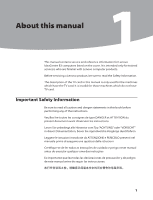
manual 1Chapter 1. About this manual This manual contains service and reference information for Lenovo IdeaCentre B3 computers listed on the cover. It is intended only for trained servicers who are familiar with Lenovo computer products. Before servicing a Lenovo écuter les instructions. Lesen Sie - Lenovo IdeaCentre B325 | Lenovo IdeaCentre B3 Hardware Maintenance Manual - Page 4
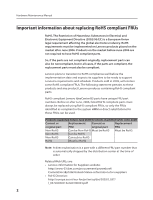
Maintenance Manual Important information support Lenovo's requirements and schedule. Products sold in 2005, will contain some RoHS compliant FRUs. The following statement pertains to these products and any product Lenovo produces containing RoHS compliant parts. RoHS compliant Lenovo IdeaCentre - Lenovo IdeaCentre B325 | Lenovo IdeaCentre B3 Hardware Maintenance Manual - Page 5
Chapter 1. About this manual •• California Senate Bills 20, 50: http://www.ciwmb.ca.gov/HHW/Events/AnnualConf/2004/ presentation/MPaparian.pdf 3 - Lenovo IdeaCentre B325 | Lenovo IdeaCentre B3 Hardware Maintenance Manual - Page 6
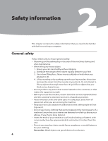
Hardware Maintenance Manual Safety information 2 This chapter contains the safety information that you need to be familiar with before servicing a computer. General safety Follow these rules to ensure general safety: •• Observe good housekeeping in the area of the machines during and after - Lenovo IdeaCentre B325 | Lenovo IdeaCentre B3 Hardware Maintenance Manual - Page 7
working in any other conditions that might be hazardous to your eyes. •• After service, reinstall all safety shields, guards, labels, and ground wires. Replace any networks, and modems before you open the server/workstation covers, unless instructed otherwise in the installation and configuration - Lenovo IdeaCentre B325 | Lenovo IdeaCentre B3 Hardware Maintenance Manual - Page 8
electrical circuits with the reflective surface of a plastic dental mirror. The surface is conductive; such touching can cause personal injury and machine damage. •• Do not service the following parts with the power on when they are removed from their normal operating places in a machine: - Power - Lenovo IdeaCentre B325 | Lenovo IdeaCentre B3 Hardware Maintenance Manual - Page 9
users and service personnel from injury. This guide features or options not covered by this inspection guide. If any unsafe conditions are present, you must determine how serious the apparent hazard could be and whether you can continue without first correcting the problem off the computer. Disconnect - Lenovo IdeaCentre B325 | Lenovo IdeaCentre B3 Hardware Maintenance Manual - Page 10
Manual Handling electrostatic discharge-sensitive devices Any computer eliminate static on your body. •• Prevent the part from touching your clothing. Most clothing is insulative and retains a charge below, to provide protection that meets the specific service requirement. Note: The use of a - Lenovo IdeaCentre B325 | Lenovo IdeaCentre B3 Hardware Maintenance Manual - Page 11
any equipment that will be attached to this product. •• When possible, use one hand only to connect or disconnect signal cables. •• Never turn on any systems, networks, and modems before you open the device covers, unless instructed otherwise in the installation and configuration procedures. - Lenovo IdeaCentre B325 | Lenovo IdeaCentre B3 Hardware Maintenance Manual - Page 12
Manual •• Heat to more than 100°C (212°F) •• Repair or disassemble Dispose of the battery as required by local ordinances or regulations. to hazardous laser radiation. There are no serviceable parts inside the device. •• Use of the following: Laser radiation when open. Do not stare into the beam, do - Lenovo IdeaCentre B325 | Lenovo IdeaCentre B3 Hardware Maintenance Manual - Page 13
the power switch on the power supply do not turn off the electrical current supplied to the device. The device also might have more than one power cord. To remove all electrical current from the device, ensure that all power cords are disconnected from the power source. 2 1 CAUTION: Do not place - Lenovo IdeaCentre B325 | Lenovo IdeaCentre B3 Hardware Maintenance Manual - Page 14
that applies to all machine types supported by this publication. Specifications This section lists the physical specifications for your computer. Type Lenovo IdeaCentre B3 This section lists the physical specifications. Environment Air temperature: Operating: 10° to 35°C Transit: -20° to 55 - Lenovo IdeaCentre B325 | Lenovo IdeaCentre B3 Hardware Maintenance Manual - Page 15
FRUs, ensure that the latest level of BIOS is installed on the system. A down-level BIOS might cause false errors and unnecessary replacement of the system board. Use the following procedure to help determine the cause of the problem: 1. Power-off the computer and all external devices. 2. Check all - Lenovo IdeaCentre B325 | Lenovo IdeaCentre B3 Hardware Maintenance Manual - Page 16
determination. If possible, have this information available when requesting assistance from Service Support and Engineering functions. •• Machine type and model •• Processor or hard disk upgrades •• Failure symptom - Do diagnostics indicate a failure? - What, when, where, single, or multiple systems - Lenovo IdeaCentre B325 | Lenovo IdeaCentre B3 Hardware Maintenance Manual - Page 17
using this method, repeatedly press and release the F1 key rather than leaving it pressed when turning on the computer. b. If a Power-On Password or an administrator password has been set, the Setup Utility program menu used to perform various tasks are displayed on the right side of each screen. 15 - Lenovo IdeaCentre B325 | Lenovo IdeaCentre B3 Hardware Maintenance Manual - Page 18
rules: • Must have at least seven characters in length • Contain at least one alphabetic character and one numeric character • Setup Utility program and hard disk drive passwords are not case sensitive • Not be your name or your user name • Not be a common word or a common name • Be significantly - Lenovo IdeaCentre B325 | Lenovo IdeaCentre B3 Hardware Maintenance Manual - Page 19
on page 16). 2. From Security menu, select Set Administrator Password and press Enter. 3. The password dialog box will be displayed. Type the new password, and press Enter. 4. when prompted to confirm the password, type the password again. If you type the password correctly, the password will - Lenovo IdeaCentre B325 | Lenovo IdeaCentre B3 Hardware Maintenance Manual - Page 20
Manual 1. Start the Setup Utility program (See Starting the Setup Utility program .) 2. From the Security menu, select Set Power-On Password and press Enter. 3. The password dialog box will be displayed. Type the new user access to the following device USB Setup When this feature screen. 18 - Lenovo IdeaCentre B325 | Lenovo IdeaCentre B3 Hardware Maintenance Manual - Page 21
Chapter 5. Using the Setup Utility Selecting a startup device If your computer does not start up (boot) from a device such as the CD-ROM, diskette, or hard disk as expected, use one of the following procedures to select a startup device. Selecting a temporary startup device Use this procedure to - Lenovo IdeaCentre B325 | Lenovo IdeaCentre B3 Hardware Maintenance Manual - Page 22
Hardware Maintenance Manual Exiting from the Setup Utility program When you finish viewing or changing settings, press Esc to return to the Setup Utility program menu (you might have to press Esc several times). If you want to save the new settings, select Save changes and Exit before you exit. - Lenovo IdeaCentre B325 | Lenovo IdeaCentre B3 Hardware Maintenance Manual - Page 23
be used to help you decide which FRUs to have available when servicing a computer. If you are unable to correct the problem using this index, go to "Undetermined problems" on page 27. Notes • If you have both an error message on Install an operating system on the the boot drive. boot drive. 21 - Lenovo IdeaCentre B325 | Lenovo IdeaCentre B3 Hardware Maintenance Manual - Page 24
• Checks the memory operation • Starts the video operation • Verifies that the boot drive is working If the POST detects a problem, an error message appears on the screen. A single problem can cause several error messages to appear. When you correct the cause of the first error message, the other - Lenovo IdeaCentre B325 | Lenovo IdeaCentre B3 Hardware Maintenance Manual - Page 25
CMOS Date/Time Not Set Fan Detect Error CMOS Checksum Bad Hard Disk Error Keyboard error System Halted Reboot and Select proper Boot device or time in AMI BIOS Setup. The Fan is bad or stop rotation. Make sure the Fan device is working. Checksum of CMOS is incorrect. The computer loads the default - Lenovo IdeaCentre B325 | Lenovo IdeaCentre B3 Hardware Maintenance Manual - Page 26
Maintenance Manual Undetermined problems If this computer has a parallel ATA hard disk drive, make sure that the hard disk drive is jumpered as a master and the optical drive is jumpered as a slave. 1. Power-off the computer. 2. Remove or disconnect the following components (if installed) one at - Lenovo IdeaCentre B325 | Lenovo IdeaCentre B3 Hardware Maintenance Manual - Page 27
help locate the various connectors, controls and components of the computer. Locating components and connectors The following illustrations will help you to locate the various components and connectors in your computer. Internal components The following illustration shows the components inside your - Lenovo IdeaCentre B325 | Lenovo IdeaCentre B3 Hardware Maintenance Manual - Page 28
Hardware Maintenance Manual 1 Computer stand 2 Computer cover 3 Motherboard 4 Shell 5 Plastic frame 6 Chassis 7 LED panel 8 Front bezel 9 Camera 10 Optical disk drive 11 Hard disk drive 12 Motherboard cover 13 System fan 14 Heatsink 15 Function panel 16 Invert board 17 WLAN module 18 Bluetooth - Lenovo IdeaCentre B325 | Lenovo IdeaCentre B3 Hardware Maintenance Manual - Page 29
connector 6 Headphone connector 7 Microphone connector 8 USB connector 9 Speaker connectors 10 USB connectors (4) 11 Ethernet connector 12 1394 connector 13 PS/2 keyboard connector 14 Power connector 15 WLAN connector 16 TV tuner card connector 17 Power button connector 18 Function panel connector - Lenovo IdeaCentre B325 | Lenovo IdeaCentre B3 Hardware Maintenance Manual - Page 30
Hardware Maintenance Manual 21 SATA connector 22 LED panel connector 28 - Lenovo IdeaCentre B325 | Lenovo IdeaCentre B3 Hardware Maintenance Manual - Page 31
in the Hardware Maintenance Manual (HMM) for the computer. To obtain copies of the Safety and Warranty Guide or HMM, go to the Support Web site at: http://consumersupport.lenovo.com. Note Use only parts provided by Lenovo. General information Pre-disassembly instructions Before proceeding with the - Lenovo IdeaCentre B325 | Lenovo IdeaCentre B3 Hardware Maintenance Manual - Page 32
Maintenance Manual Removing the computer stand Attention Turn off the computer and wait 3 to 5 minutes to let the computer cool down before removing the computer stand. To remove the computer stand: Note For this procedure, it helps to place the computer face-down on a soft flat surface. Lenovo - Lenovo IdeaCentre B325 | Lenovo IdeaCentre B3 Hardware Maintenance Manual - Page 33
Chapter 8. Replacing hardware 1 2 5. Remove the 2 screws that secure the computer stand to the chassis. 6. Slide out the computer stand. 4 3 3 Warning When finish replacing a FRU, follow the bellowing instructions to install back computer stand. Incorrect operations may damage the computer stand. 31 - Lenovo IdeaCentre B325 | Lenovo IdeaCentre B3 Hardware Maintenance Manual - Page 34
3 to 5 minutes to let the computer cool down before removing the computer cover. Note For this procedure, it helps to place the computer face-down on a soft flat surface. Lenovo recommends that you use a blanket, towel, or other soft cloth to protect the touch screen surface from scratches or other - Lenovo IdeaCentre B325 | Lenovo IdeaCentre B3 Hardware Maintenance Manual - Page 35
) from the drives, shut down the operating system, turn off all attached devices, and the computer. 2. Unplug all power cords from electrical outlets. 3. Disconnect all cables attached to the computer. This includes power cords, input/output (I/O) cables, and any other cables that are connected to - Lenovo IdeaCentre B325 | Lenovo IdeaCentre B3 Hardware Maintenance Manual - Page 36
insert the new memory module into the socket and push down on the top edge of the memory module. Make sure the latches lock the memory module in place. 9. Align then slide back the memory cover. 10. Screw the memory cover back. Replacing the optical disk drive Attention Turn off the computer and - Lenovo IdeaCentre B325 | Lenovo IdeaCentre B3 Hardware Maintenance Manual - Page 37
drive Note Chapter 8. Replacing hardware For this procedure, it helps to place the computer face-down on a soft flat surface. Lenovo recommends that you use a blanket, towel, or other soft cloth to protect the screen surface from scratches or other damage. 1. Remove any media (diskettes, CDs, or - Lenovo IdeaCentre B325 | Lenovo IdeaCentre B3 Hardware Maintenance Manual - Page 38
bay. 10. Screw the new optical drive back to the chassis. Removing the computer cover To remove the computer cover: Note For this procedure, it helps to place the computer face-down on a soft flat surface. Lenovo recommends that you use a blanket, towel, or other soft cloth to protect the screen - Lenovo IdeaCentre B325 | Lenovo IdeaCentre B3 Hardware Maintenance Manual - Page 39
connectors on the rear of the computer". 4. Remove the computer stand. Refer to "Removing the computer stand". 5. Lift up the computer cover gently from the bottom right corner to release the cover from the setscrews . 2 2 2 2 2 2 2 1 2 2 Replacing the hard disk drive Attention Turn off the - Lenovo IdeaCentre B325 | Lenovo IdeaCentre B3 Hardware Maintenance Manual - Page 40
Maintenance Manual To replace the hard disk drive: Note For this procedure, it helps to place the computer face-down on a soft flat surface. Lenovo recommends that you use a blanket, towel, or other soft cloth to protect the screen surface from scratches or other damage. 1. Remove the computer stand - Lenovo IdeaCentre B325 | Lenovo IdeaCentre B3 Hardware Maintenance Manual - Page 41
the new hard disk drive into the drive bay. (2) Screw back the 4 screws on the drive bay. 8. Connect the data and power cables back to the hard disk drive. 9. Align the 4 screw holes in the hard disk drive bay with the mounting holes in the chassis, then screw it back. 10. Install the computer cover - Lenovo IdeaCentre B325 | Lenovo IdeaCentre B3 Hardware Maintenance Manual - Page 42
Manual 4. Disconnect the antenna cable from the bluetooth module. 5. Connect the antenna cable to the new bluetooth module. 6. Align then use double-sided sticky tape stick the bluetooth module back. 7. Install the computer cover and stand. Removing the motherboard cover 1. Remove the computer - Lenovo IdeaCentre B325 | Lenovo IdeaCentre B3 Hardware Maintenance Manual - Page 43
the heatsink To remove the heatsink: 1. Removing the computer stand. Refer to "Removing the computer stand". 2. Removing the computer cover. Refer to "Removing the computer cover". 3. Removing the motherboard cover. Refer to "Removing the motherboard cover". 4. Remove the 4 screws that secure the - Lenovo IdeaCentre B325 | Lenovo IdeaCentre B3 Hardware Maintenance Manual - Page 44
Manual 5. Lift up the heatsink. 6. Align then install the new heatsink. 7. Align then install the motherboard cover back. 8. Align then install the computer cover and computer stand. Replacing the system fan To remove the system fan: 1. Removing the computer stand. Refer to "Removing the computer - Lenovo IdeaCentre B325 | Lenovo IdeaCentre B3 Hardware Maintenance Manual - Page 45
it up to remove it. 8. Align then install the new system fan. 9. Align then install the heatsink & the motherboard cover back. 10. Align then install the computer cover and computer stand. Replacing the microprocessor Important Do not touch the gold contact on the bottom of the microprocessor. When - Lenovo IdeaCentre B325 | Lenovo IdeaCentre B3 Hardware Maintenance Manual - Page 46
Hardware Maintenance Manual 6. Lift the microprocessor out of the retainer. 7. Align then place the new microprocessor back and lock the retainer properly with the handle. 8. Align then install the heatsink and the motherboard cover. 9. Install the computer cover and computer stand. Replacing the - Lenovo IdeaCentre B325 | Lenovo IdeaCentre B3 Hardware Maintenance Manual - Page 47
the cable to the new function panel. 8. Install the computer cover and computer stand. Replacing the WLAN card card 1. Remove the computer stand. Refer to "Removing the computer stand". 2. Remove the computer cover. Refer to "Removing the computer cover". 3. Remove the motherboard cover. Refer to - Lenovo IdeaCentre B325 | Lenovo IdeaCentre B3 Hardware Maintenance Manual - Page 48
out the WLAN card. 6. Align then insert the new WLAN card to the card port and screw it in to the motherboard. 7. Connect the antenna cables back to the new WLAN card. 8. Install the motherboard cover back. 9. Install the computer cover and computer stand. Replacing the speakers system 1. Remove the - Lenovo IdeaCentre B325 | Lenovo IdeaCentre B3 Hardware Maintenance Manual - Page 49
speakers system. Chapter 8. Replacing hardware 7. Align then screw in the new speakers system. 8. Connect the new speakers cables to the motherboard. 9. Install the motherboard cover back. 10. Install the computer cover and computer stand. Removing the inverter board To remove the inverter board - Lenovo IdeaCentre B325 | Lenovo IdeaCentre B3 Hardware Maintenance Manual - Page 50
then screw in the new inverter board. 9. Install the optical disk drive. 10. Install the computer cover and computer stand. Replacing the TV tuner card To replace the TV tuner card 1. Remove the computer stand. Refer to "Removing the computer stand". 2. Remove the computer cover. Refer to "Removing - Lenovo IdeaCentre B325 | Lenovo IdeaCentre B3 Hardware Maintenance Manual - Page 51
screw in the new TV tuner card. 8. Connect the antenna cable to the new TV tuner card. 9. Screw back the motherboard cover. 10. Install the computer cover and screw back the computer stand. Removing the TV antenna connector To remove the TV antenna connector: 1. Remove the computer stand. Refer to - Lenovo IdeaCentre B325 | Lenovo IdeaCentre B3 Hardware Maintenance Manual - Page 52
WLAN card. Refer to "Replacing the WLAN card". 8. Remove the TV tuner card. Refer to "Replacing the TV tuner card". 9. Remove the TV antenna connector. Refer to "Removing the TV antenna connector". 10. Remove all the cables that connected to the motherboard. 11. Remove the 8 screws that secure the - Lenovo IdeaCentre B325 | Lenovo IdeaCentre B3 Hardware Maintenance Manual - Page 53
back the TV antenna connector to the new motherboard. 14. Align then screw in the new motherboard to the chassis. 15. Install all related components back to the new motherboard. 16. Connect all the cables to the new motherboard. 17. Screw back the motherboard cover. 18. Install the computer cover - Lenovo IdeaCentre B325 | Lenovo IdeaCentre B3 Hardware Maintenance Manual - Page 54
Hardware Maintenance Manual 4. Lift up the shell. Replacing the camera To replace the camera 1. Remove the computer stand. Refer to "Removing the computer stand". 2. Remove the computer cover. Refer to "Removing the computer cover". 3. Remove the shell. Refer to "Removing the shell" 4. Pull the pins - Lenovo IdeaCentre B325 | Lenovo IdeaCentre B3 Hardware Maintenance Manual - Page 55
the camera. 4. Connect the cable to the new camera. 5. Align then screw in the new camera. 6. Align then screw back the shell. 7. Install the computer cover and screw back the computer stand. Replacing the touch module To replace the touch module: 1. Remove the computer stand. Refer to "Removing the - Lenovo IdeaCentre B325 | Lenovo IdeaCentre B3 Hardware Maintenance Manual - Page 56
to the new touch module. 8. Align then screw the new touch module back. 9. Install the computer cover and screw back the computer stand. Replacing the LED panel To replace the LED panel 1. Remove the computer stand. Refer to "Removing the computer stand". 2. Remove the optical disk drive. Refer - Lenovo IdeaCentre B325 | Lenovo IdeaCentre B3 Hardware Maintenance Manual - Page 57
the LED cable from the LED panel. 8. Remove the shell. Refer to "Removing the shell". 9. Remove the 6 screws that secure chassis to the front bezel. 10. Pull the pins to release the chassis from the front bezel. 11. Place the computer upside down and separate the chassis from the front bezel. 55 - Lenovo IdeaCentre B325 | Lenovo IdeaCentre B3 Hardware Maintenance Manual - Page 58
cable that connected to the LED panel. 14. Align then place the new LED panel to the chassis. 15. Connect all the cables to the new LED panel, and screw in the new LED panel to the chassis. 16. Install all relative parts back. 17. Install the computer back cover and screw back the - Lenovo IdeaCentre B325 | Lenovo IdeaCentre B3 Hardware Maintenance Manual - Page 59
safety information" in the Safety and Warranty Guide that was included with your computer or in the Hardware Maintenance Manual (HMM) for the computer. To obtain copies of the Safety and Warranty Guide or HMM, go to the Support Web site at: http://consumersupport.lenovo.com. To replace the keyboard - Lenovo IdeaCentre B325 | Lenovo IdeaCentre B3 Hardware Maintenance Manual - Page 60
information" in the Safety and Warranty Guide that was included with your computer or in the Hardware Maintenance Manual (HMM) for the computer. To obtain copies of the Safety and Warranty Guide or HMM, go to the Support Web site at: http://consumersupport.lenovo.com. To replace the mouse: 1. Remove - Lenovo IdeaCentre B325 | Lenovo IdeaCentre B3 Hardware Maintenance Manual - Page 61
information" in the Safety and Warranty Guide that was included with your computer or in the Hardware Maintenance Manual (HMM) for the computer. To obtain copies of the Safety and Warranty Guide or HMM, go to the Support Web site at: http://consumersupport.lenovo.com. To replace the power cord - Lenovo IdeaCentre B325 | Lenovo IdeaCentre B3 Hardware Maintenance Manual - Page 62
is allowed to control the power management features of the computer and the setting for Advanced Power Management (APM) BIOS mode is ignored. Not all operating systems support ACPI BIOS mode. Automatic Power-On features The Automatic Power-On features within the Power Management menu allow you - Lenovo IdeaCentre B325 | Lenovo IdeaCentre B3 Hardware Maintenance Manual - Page 63
according to the instructions and requirements described in the manuals included with your computer. Lenovo will not assume responsibility for any loss incurred except those resulting from installation or operations carried out by Lenovo professional service staff. Lenovo has made every attempt - Lenovo IdeaCentre B325 | Lenovo IdeaCentre B3 Hardware Maintenance Manual - Page 64
product and the manuals included with your computer. For the latest information or if you have any questions or comments, please visit the consumer support website at: http://consumersupport.lenovo.com. Lenovo is a registered trademark of Lenovo. Microsoft, Windows, and Windows Vista are trademarks
-
 1
1 -
 2
2 -
 3
3 -
 4
4 -
 5
5 -
 6
6 -
 7
7 -
8
-
9
-
10
-
11
-
12
-
13
-
14
-
15
-
16
-
17
-
18
-
19
-
20
-
21
-
22
-
23
-
24
-
25
-
26
-
27
-
28
-
29
-
30
-
31
-
32
-
33
-
34
-
35
-
36
-
37
-
38
-
39
-
40
-
41
-
42
-
43
-
44
-
45
-
46
-
47
-
48
-
49
-
50
-
51
-
52
-
53
-
54
-
55
-
56
-
57
-
58
-
59
-
60
-
61
-
62
-
63
-
64
 |
 |

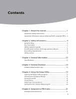
Contents
i
Contents
Chapter 1. About this manual
................................................
1
Important
Safety Information
......................................................................
1
Important information about replacing RoHS compliant FRUs ..2
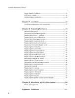
Chapter 2. Safety information
................................................
4
General safety
.......................................................................................................
4
Electrical safety
....................................................................................................
5
Safety inspection guide
...................................................................................
7
Handling electrostatic discharge-sensitive devices
.........................
8
Grounding requirements
...............................................................................
8
Safety notices
........................................................................................................
9
Chapter 3. General information
...........................................
12
Specifications
.....................................................................................................
12
Chapter 4. General Checkout
...............................................
13
Problem determination tips
.......................................................................
14
Chapter 5. Using the Setup Utility
......................................
15
Starting the Setup Utility program
.........................................................
15
Viewing and changing settings
................................................................
15
Using passwords
..............................................................................................
16
Using Device
......................................................................................................
18
Selecting a startup device
...........................................................................
19
Exiting from the Setup Utility program
................................................
20
Chapter 6. Symptom-to-FRU Index
.....................................
21
Hard disk drive boot error
...........................................................................
21