Lenovo IdeaCentre K330 Lenovo IdeaCentre K3 Series Hardware Maintenance Manual - Page 50
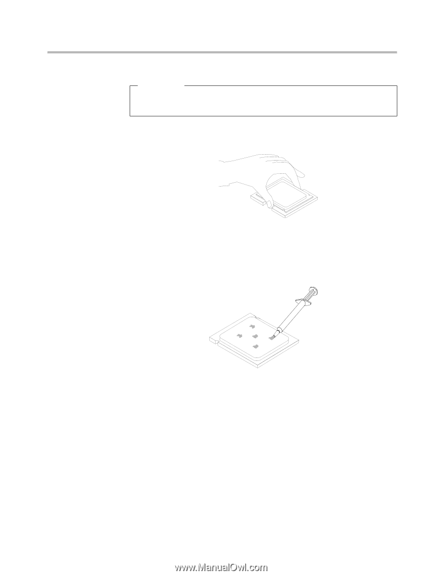
Important, To avoid damaging the microprocessor contacts, do not tilt the, microprocessor when
 |
View all Lenovo IdeaCentre K330 manuals
Add to My Manuals
Save this manual to your list of manuals |
Page 50 highlights
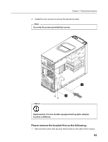
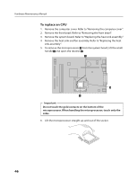
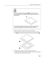
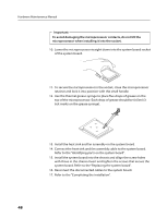
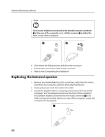
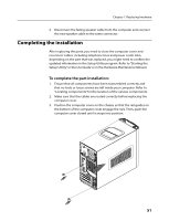
Hardware Maintenance Manual Important To avoid damaging the microprocessor contacts, do not tilt the microprocessor when installing it into the socket. 10. Lower the microprocessor straight down into the system board socket of the system board. 11. To secure the microprocessor in the socket, close the microprocessor retainer and lock it into position with the small handle. 12. Use the thermal grease syringe to place five drops of grease on the top of the microprocessor. Each drop of grease should be 0.03ml (3 tick marks on the grease syringe). 13. Install the heat sink and fan assembly on the system board. 14. Connect the heat sink and fan assembly cable to the system board. Refer to the "Identifying parts on the system board". 15. Install the system board into the chassis and allign the screw holes with those in the chassis.Insert and tighten the screws that secure the system board. Refer to the "Replacing the system board". 16. Reconnect the disconnected cables to the system board. 17. Refer to the "Completing the installation". 48
-
 1
1 -
2
-
3
-
4
-
5
-
6
-
7
-
8
-
9
-
10
-
11
-
12
-
13
-
14
-
15
-
16
-
17
-
18
-
19
-
20
-
21
-
22
-
23
-
24
-
25
-
26
-
27
-
28
-
29
-
30
-
31
-
32
-
33
-
34
-
35
-
36
-
37
-
38
-
39
-
40
-
41
-
42
-
43
-
44
-
 45
45 -
 46
46 -
 47
47 -
 48
48 -
 49
49 -
 50
50 -
 51
51 -
 52
52 -
 53
53 -
 54
54 -
 55
55 -
56
-
57
 |
 |