Lenovo IdeaPad A1-07 Hardware Maintenance Manual - Page 36
Screw quantity, Color, Torque - gps
 |
View all Lenovo IdeaPad A1-07 manuals
Add to My Manuals
Save this manual to your list of manuals |
Page 36 highlights
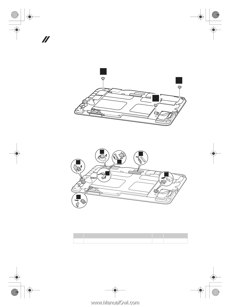
A1-07 HMM_EN.book Page 32 Wednesday, September 28, 2011 5:06 PM Lenovo IdeaPad Tablet A1-07 Hardware Maintenance Manual Figure 3. Removal steps of system board Remove three screws a. 1 1 1 Unplug the Speaker connector h , detach LCD connector b , Touch connector c , Front Camera e , Volume up/down key connector g , peel off the vibrator d , and disconnect the GPS antenna cable f . 4 2 5 3 6 8 7 Note In step 2 , unplug the GPS antenna jack by using the removal tool antenna RF connector (P/N: 08K7159), or pick up the connector with your fingers and gently unplug it in the direction shown by arrow. Step Screw (quantity) a 5SX16017M_1, flat-head, nylok-coated (3) Color Torque White 2.0 ~ 2.5 kgfcm 32
-
 1
1 -
2
-
3
-
4
-
5
-
6
-
7
-
8
-
9
-
10
-
11
-
12
-
13
-
14
-
15
-
16
-
17
-
18
-
19
-
20
-
21
-
22
-
23
-
24
-
25
-
26
-
27
-
28
-
29
-
30
-
 31
31 -
 32
32 -
 33
33 -
 34
34 -
 35
35 -
 36
36 -
 37
37 -
 38
38 -
 39
39 -
 40
40 -
 41
41 -
42
-
43
-
44
-
45
-
46
-
47
-
48
-
49
-
50
 |
 |
Lenovo IdeaPad Tablet A1-07 Hardware Maintenance Manual
32
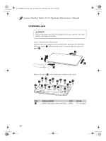
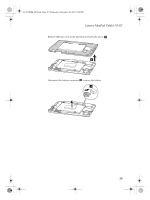
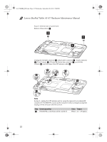
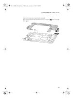
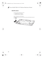
Figure 3. Removal steps of system board
Remove three screws
Unplug the
Speaker connector
, detach LCD connector
, Touch connector
, Front Camera
, Volume up/down key connector
, peel off the
vibrator
, and disconnect the GPS antenna cable
.
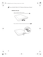
Note
In step 2 , unplug the GPS antenna jack by using the removal tool antenna RF
connector (P/N: 08K7159), or pick up the connector with your fingers and gently
unplug it in the direction shown by arrow.
Step
Screw (quantity)
Color
Torque
5SX16017M_1, flat-head, nylok-coated (3)
White
2.0 ~ 2.5 kgfcm
a
1
1
1
h
b
c
e
g
d
f
7
6
4
5
3
2
8
a
A1-07 HMM_EN.book
Page 32
Wednesday, September 28, 2011
5:06 PM