Lenovo IdeaPad P500 Touch Hardware Maintenance Manual
Lenovo IdeaPad P500 Touch Manual
 |
View all Lenovo IdeaPad P500 Touch manuals
Add to My Manuals
Save this manual to your list of manuals |
Lenovo IdeaPad P500 Touch manual content summary:
- Lenovo IdeaPad P500 Touch | Hardware Maintenance Manual - Page 1
Lenovo IdeaPad Z500/P500 Hardware Maintenance Manual - Lenovo IdeaPad P500 Touch | Hardware Maintenance Manual - Page 2
and the product it supports, be sure to read the general information under "Notices" on page 85. First Edition (Sep. 2012) © Copyright Lenovo 2012. All rights reserved. LIMITED AND RESTRICTED RIGHTS NOTICE: If data or software is delivered pursuant a General Services Administration "GSA" contract - Lenovo IdeaPad P500 Touch | Hardware Maintenance Manual - Page 3
Screen blank mode 25 Sleep (standby) mode 25 Lenovo IdeaPad Z500/P500 26 Specifications 26 Status indicators 28 Function key combinations 29 FRU replacement notices 30 Screw notices 30 Removing and replacing an FRU 31 1010 Keyboard 32 1020 Optical drive 34 1030 Base cover 36 1040 Battery - Lenovo IdeaPad P500 Touch | Hardware Maintenance Manual - Page 4
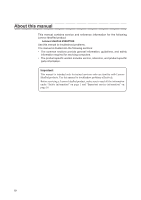
About this manual This manual contains service and reference information for the following Lenovo IdeaPad product: Lenovo IdeaPad Z500/P500 Use this manual to troubleshoot problems. The manual is divided into the following sections: •• The common sections provide general information, guidelines, and - Lenovo IdeaPad P500 Touch | Hardware Maintenance Manual - Page 5
following safety information that you need to get familiar with before you service an Lenovo IdeaPad Z500/P500 computer: •• "General safety" on page 2 •• "Electrical safety" on page 3 •• "Safety inspection guide" on page 5 •• "Handling devices that are sensitive to electrostatic discharge" on page - Lenovo IdeaPad P500 Touch | Hardware Maintenance Manual - Page 6
IdeaPad Z500/P500 Hardware Maintenance Manual service representatives and the customer are not in a hazardous position. •• Place removed covers working in any other conditions that may be hazardous to your eyes. •• After service, reinstall all safety shields, guards, labels, and ground wires. Replace - Lenovo IdeaPad P500 Touch | Hardware Maintenance Manual - Page 7
- Performing a mechanical inspection - Working near power supplies - Removing or installing main units •• Before you start to work on the machine, unplug the Observe the special safety precautions when you work with very high voltages; instructions for these precautions are in the safety sections - Lenovo IdeaPad P500 Touch | Hardware Maintenance Manual - Page 8
IdeaPad Z500/P500 Hardware Maintenance Manual •• Always look carefully for possible hazards in your work area. Examples of these hazards are moist floors, nongrounded power extension cables, power surges, and missing safety grounds. •• Do not touch live electrical circuits with the reflective - Lenovo IdeaPad P500 Touch | Hardware Maintenance Manual - Page 9
and built, required safety items were installed to protect users and service personnel from injury. This guide addresses only those items. You should use good judgment to identify potential safety hazards according to the attachment of non-Lenovo IdeaPad features or options not covered by this - Lenovo IdeaPad P500 Touch | Hardware Maintenance Manual - Page 10
IdeaPad Z500/P500 Hardware Maintenance Manual service requirement. Note: The use of a grounding system to guard against ESD damage is desirable but not necessary. - Attach the ESD ground clip to any frame ground, ground braid, or greenwire ground. - When working on a double-insulated or battery - Lenovo IdeaPad P500 Touch | Hardware Maintenance Manual - Page 11
this section are provided in English, French, German, Hebrew, Italian, Japanese, and Spanish. Safety notice 1 Before the computer is powered on after FRU replacement, make sure all screws, springs, and other small parts are in place and are not left loose inside the computer. Verify this by shaking - Lenovo IdeaPad P500 Touch | Hardware Maintenance Manual - Page 12
IdeaPad Z500/P500 Hardware Maintenance Manual Safety notice 2 DANGER Some standby batteries contain a small amount of nickel and cadmium. Do not disassemble a standby battery, recharge it, throw it into fire or water, or shortcircuit it. Dispose of the battery as required by local ordinances or - Lenovo IdeaPad P500 Touch | Hardware Maintenance Manual - Page 13
of nickel. Do not disassemble it, throw it into fire or water, or short-circuit it. Dispose of the battery pack as required by local ordinances or regulations. Use only the battery in the appropriate parts listing when replacing the battery pack. Use of an incorrect battery can result in ignition - Lenovo IdeaPad P500 Touch | Hardware Maintenance Manual - Page 14
IdeaPad Z500/P500 Hardware Maintenance Manual Safety notice 4 DANGER The lithium battery can cause a fire, an explosion, or a severe burn. Do not recharge it, remove its polarized connector, disassemble it, heat it above 100°C (212°F), incinerate it, or expose its cell contents to water. Dispose of - Lenovo IdeaPad P500 Touch | Hardware Maintenance Manual - Page 15
your hands, immediately wash the affected areas with water at least for 15 minutes. Seek medical care if any symptoms caused by the fluid are le mani, lavare immediatamente le parti interessate con acqua corrente per almeno 15 minuti; poi consultare un medico se i sintomi dovessero permanere. Si la - Lenovo IdeaPad P500 Touch | Hardware Maintenance Manual - Page 16
IdeaPad Z500/P500 Hardware Maintenance Manual Safety notice 6 DANGER To avoid shock, do not remove the plastic cover that protects the Materialien zu entzünden oder Verletzungen bei Personen hervorzurufen. Sebbene le batterie di alimentazione siano a basso voltaggio, una batteria in corto circuito - Lenovo IdeaPad P500 Touch | Hardware Maintenance Manual - Page 17
computer, unplug all power cords from electrical outlets, remove the battery pack, and then disconnect any interconnecting cables. Avant tous les cordons d'alimentation des socles de prise de courant, retirez la batterie et déconnectez tous les cordons d'interface. Die Stromzufuhr muß abgeschaltet, - Lenovo IdeaPad P500 Touch | Hardware Maintenance Manual - Page 18
Z500/P500 Hardware Maintenance Manual Laser compliance statement Some models of Lenovo IdeaPad computer are equipped from the factory with an optical storage device such as a CD-ROM drive or a DVD-ROM drive. Such devices are also sold separately as options. If one of these drives is installed, it - Lenovo IdeaPad P500 Touch | Hardware Maintenance Manual - Page 19
Safety information A CD-ROM drive, a DVD-ROM drive, or any other storage device installed may contain an embedded Class 3A or Class 3B laser diode. Note the following: DANGER Emits visible and invisible laser radiation con instrumental óptico el haz de luz. Evite la exposición directa al haz. 15 - Lenovo IdeaPad P500 Touch | Hardware Maintenance Manual - Page 20
-installable. The BIOS and device drivers are posted on the customer support site: http://consumersupport.lenovo.com/. Strategy for replacing FRUs Before replacing parts: Make sure that all software fixes, drivers, and BIOS downloads are installed before replacing any FRUs listed in this manual - Lenovo IdeaPad P500 Touch | Hardware Maintenance Manual - Page 21
for replacing and servicing FRUs: •• If you are instructed to replace an FRU, but the replacement does not solve the problem, reinstall for replacing a hard disk drive Always try to run a low-level format before replacing a hard disk drive. This will cause all customer data on the hard disk to - Lenovo IdeaPad P500 Touch | Hardware Maintenance Manual - Page 22
IdeaPad Z500/P500 Hardware Maintenance Manual Important information about replacing RoHS compliant support Lenovo's requirements and schedule in the EU. Products sold in 2005 and 2006 will contain some RoHS compliant FRUs. The following statement pertains to these products and any product Lenovo - Lenovo IdeaPad P500 Touch | Hardware Maintenance Manual - Page 23
removing and replacing FRUs. • When you replace FRUs, use new nylon-coated screws. • Be extremely careful during such write operations as copying, saving, or formatting. Drives in the computer that you are servicing software errors. Consider replacing an FRU only when a problem recurs. If you - Lenovo IdeaPad P500 Touch | Hardware Maintenance Manual - Page 24
a liquid onto the keyboard •• Use of an incorrect AC adapter on laptop products The following symptoms might indicate damage caused by nonwarranted activities: •• Missing parts might be a symptom of unauthorized service or modification. •• If the spindle of a hard disk drive becomes noisy, it may - Lenovo IdeaPad P500 Touch | Hardware Maintenance Manual - Page 25
battery pack supplies power when you turn on the computer. If you suspect a power problem, servicing. 3. If the voltage is not correct, replace the AC adapter. 4. If the voltage is acceptable, do the following: •• Replace the system board. •• If the problem continues, go to "Lenovo IdeaPad Z500/P500 - Lenovo IdeaPad P500 Touch | Hardware Maintenance Manual - Page 26
IdeaPad Z500/P500 Hardware Maintenance Manual Perform operational charging. If the battery status indicator or icon does not light on, remove the battery pack and let it return to room temperature. Reinstall the battery pack. If the charge indicator or icon is still off, replace the battery pack. If - Lenovo IdeaPad P500 Touch | Hardware Maintenance Manual - Page 27
using OneKey Recovery Restore of factory default The Lenovo IdeaPad Z500/P500 computers come with pre-installed OneKey Recovery System.In order to save application files and the initial backed up files of the system, the hard disk in a Lenovo computer includes a hidden partition when it is shipped - Lenovo IdeaPad P500 Touch | Hardware Maintenance Manual - Page 28
Utility. The user must enter the SVP in order to get access to the BIOS Setup Utility and change the system configuration. Attention: If the SVP has been forgotten and cannot be made available to the servicer, there is no service procedure to reset the password. The system board must be replaced for - Lenovo IdeaPad P500 Touch | Hardware Maintenance Manual - Page 29
suspend time" has been set on the timer, and the user does not do any operation with the keyboard, the hard disk, the parallel connector, or the diskette drive within that time. •• If the battery indicator is amber, indicating that the battery power is low. To cause the computer to return from sleep - Lenovo IdeaPad P500 Touch | Hardware Maintenance Manual - Page 30
/P500 Hardware Maintenance Manual Lenovo IdeaPad Z500/P500 This chapter presents the following product-specific service references and product-specific parts information: •• "Specifications" on page 26 •• "Status indicators" on page 28 •• "Function key combinations" on page 29 •• "FRU replacement - Lenovo IdeaPad P500 Touch | Hardware Maintenance Manual - Page 31
Lenovo IdeaPad Z500/P500 Table 1. Specifications (continued) Feature I/O port Audio Ethernet (on the system board) PCI Express Mini Card slot Bluetooth wireless Keyboard Touch pad Integrated camera Battery AC adapter Pre-installed operating system Description • Combo audio jack × 2 • RJ45 x 1 • - Lenovo IdeaPad P500 Touch | Hardware Maintenance Manual - Page 32
IdeaPad Z500/P500 Hardware Maintenance Manual Status indicators The system status indicators below show the computer status: 1 2 Table 2. Status indicators Indicator Indicator status On (solid white) Power Blinking Off On (solid white) On (solid amber) Battery Blinking slowly (white) - Lenovo IdeaPad P500 Touch | Hardware Maintenance Manual - Page 33
active window. : Enables/disables the touchpad. : Enables/disables Airplane mode. : Displays all currently active apps. : Turns on/off the backlight of the LCD screen. : Toggles the display between the computer and an external device. : Decreases display brightness. : Increases - Lenovo IdeaPad P500 Touch | Hardware Maintenance Manual - Page 34
IdeaPad Z500/P500 Hardware Maintenance Manual FRU replacement notices This section presents notices related to removing and replacing parts. Read this section carefully before replacing any FRU. Screw notices Loose screws can cause a reliability problem. In the Lenovo IdeaPad computer, this problem - Lenovo IdeaPad P500 Touch | Hardware Maintenance Manual - Page 35
Lenovo IdeaPad Z500/P500 Removing and replacing an FRU This section presents exploded figures with the instructions to indicate how to remove and replace the FRU. Make sure to observe the following general rules: 1. Do not attempt to service touching it, establish personal grounding by touching - Lenovo IdeaPad P500 Touch | Hardware Maintenance Manual - Page 36
IdeaPad Z500/P500 Hardware Maintenance Manual 1010 Keyboard Figure 1. Removal steps of keyboard Remove two screws 1. 1 1 Step 1 Screw (quantity) M2 × 5 mm, flat-head, nylok-coated (2) Color Black Torque 3.62 kg-cm Insert the screwdriver into one of the screw - Lenovo IdeaPad P500 Touch | Hardware Maintenance Manual - Page 37
Lenovo IdeaPad Z500/P500 Figure 1. Removal steps of keyboard (continued) Lift the keyboard a little, and then detach the connector in the direction shown by arrows 4 5. Remove the keyboard in the direction shown by arrow 6. 6 4 5 When installing: Make sure that the FPC connector is attached firmly. - Lenovo IdeaPad P500 Touch | Hardware Maintenance Manual - Page 38
IdeaPad Z500/P500 Hardware Maintenance Manual 1020 Optical drive For access, remove this FRU: •• "1010 Keyboard" on page 32 Figure 2. Removal steps of optical drive Remove the screw 1. 1 Step 1 Screw (quantity) M2.5 × 6 mm, flat-head, nylok-coated (1) Color Black Torque 8.03 kg-cm 34 - Lenovo IdeaPad P500 Touch | Hardware Maintenance Manual - Page 39
Lenovo IdeaPad Z500/P500 Figure 2. Removal steps of Optical drive (continued) Insert a screwdriver into the screw hole and push the optical drive in the direction shown by arrow 2 . Pull the optical drive out in the direction shown by arrow 3. 2 3 35 - Lenovo IdeaPad P500 Touch | Hardware Maintenance Manual - Page 40
IdeaPad Z500/P500 Hardware Maintenance Manual 1030 Base cover For access, remove this FRU: •• "1010 Keyboard" on page 32 •• "1020 Optical drive" on page 34 Figure 3. Removal steps of base cover Remove the five screws 1. 1 1 1 1 Step 1 Screw (quantity) M2.5 × 6 mm, flat-head, nylok-coated (5) - Lenovo IdeaPad P500 Touch | Hardware Maintenance Manual - Page 41
Lenovo IdeaPad Z500/P500 Figure 3. Removal steps of base cover (continued) Remove four screws 2, three screws 3 and three screws 4 on the bottom. 2 3 4 2 3 2 2 Step 2 3 4 Screw (quantity) M2 × 6 mm, flat-head, nylok-coated (4) M2 × 5 mm, flat-head, nylok-coated (3) - Lenovo IdeaPad P500 Touch | Hardware Maintenance Manual - Page 42
IdeaPad Z500/P500 Hardware Maintenance Manual Note: Applying labels to the base cover The new base cover FRU is shipped with a kit containing labels of several kinds. When you replace the base cover, you need to apply the following label: The following labels need to be peeled off from the old - Lenovo IdeaPad P500 Touch | Hardware Maintenance Manual - Page 43
Lenovo IdeaPad Z500/P500 1040 Battery pack For access, remove these FRUs in order: •• "1010 Keyboard" on page 32 •• "1020 Optical drive" on page 34 •• "1030 Base cover" on page 36 DANGER Only use the battery specified in the parts list for your computer. Any other battery could ignite or explode. - Lenovo IdeaPad P500 Touch | Hardware Maintenance Manual - Page 44
IdeaPad Z500/P500 Hardware Maintenance Manual Figure 4. Removal steps of battery pack (continued) Remove the battery pack in the direction shown by arrow 3. 3 When installing: Make sure the battery pack connector is attached firmly. 40 - Lenovo IdeaPad P500 Touch | Hardware Maintenance Manual - Page 45
Lenovo IdeaPad Z500/P500 1050 Hard disk drive For access, remove these FRUs in order: •• "1010 Keyboard" on page 32 •• "1020 Optical drive" on page 34 •• "1030 Base cover" on page 36 •• "1040 Battery pack" on page 39 Attention: • Do not drop the hard disk drive or apply any physical shock to it. - Lenovo IdeaPad P500 Touch | Hardware Maintenance Manual - Page 46
IdeaPad Z500/P500 Hardware Maintenance Manual Figure 5. Removal steps of hard disk drive (continued) Detach the HDD connector in the direction shown by arrow 2. Remove the hard disk drive from the slot in the direction shown by arrow 3. 3 2 When installing: Make sure that the HDD connector is - Lenovo IdeaPad P500 Touch | Hardware Maintenance Manual - Page 47
Lenovo IdeaPad Z500/P500 1060 PCI Express Mini Card for wireless LAN For access, remove these FRUs in order: •• "1010 Keyboard" on page 32 •• "1020 Optical drive" on page 34 •• "1030 Base cover" on page 36 •• "1040 Battery pack" on page 39 Figure 6. Removal steps of PCI Express Mini Card for - Lenovo IdeaPad P500 Touch | Hardware Maintenance Manual - Page 48
IdeaPad Z500/P500 Hardware Maintenance Manual Figure 6. Removal steps of PCI Express Mini Card for wireless LAN (continued) Remove the card in the direction shown by arrow 3. 3 When installing: •• In models with a wireless LAN card that has two antenna connectors, plug the black cable (1st) (MAIN) - Lenovo IdeaPad P500 Touch | Hardware Maintenance Manual - Page 49
Lenovo IdeaPad Z500/P500 1070 DIMM For access, remove these FRUs in order: •• "1010 Keyboard" on page 32 •• "1020 Optical drive" on page 34 •• "1030 Base cover" on page 36 •• "1040 Battery pack" on page 39 Figure 7. Removal steps of DIMM Release the two latches on both edges of the socket at the - Lenovo IdeaPad P500 Touch | Hardware Maintenance Manual - Page 50
IdeaPad Z500/P500 Hardware Maintenance Manual 1080 Fan assembly and Heat Sink assembly For access, remove these FRUs in order: •• "1010 Keyboard" on page 32 •• "1020 Optical drive" on page 34 •• "1030 Base cover" on page 36 •• "1040 Battery pack" on page 39 Figure 8. Removal steps of fan assembly - Lenovo IdeaPad P500 Touch | Hardware Maintenance Manual - Page 51
Lenovo IdeaPad Z500/P500 Figure 8. Removal steps of fan assembly and heat sink assembly roughly. Improper handling can cause distortion or deformation and imperfect contact with components. a b When installing: Before you attach the fan assembly to the computer, apply thermal grease, at an amount of - Lenovo IdeaPad P500 Touch | Hardware Maintenance Manual - Page 52
IdeaPad Z500/P500 Hardware Maintenance Manual 1090 CPU For access, remove these FRUs in order: •• "1010 Keyboard" on page 32 •• "1020 Optical drive" on page 34 •• "1030 Base cover" on page 36 •• "1040 Battery pack" on page 39 •• "1050 Hard disk drive" on page 41 •• "1060 PCI Express Mini Card for - Lenovo IdeaPad P500 Touch | Hardware Maintenance Manual - Page 53
Lenovo IdeaPad Z500/P500 1100 ODD board and LED board For access, remove these FRUs in order: •• "1010 Keyboard" on page 32 •• "1020 Optical drive" on page 34 •• "1030 Base cover" on page 36 •• "1040 Battery pack" on page 39 •• "1050 Hard disk drive" on page 41 •• "1060 PCI Express Mini Card for - Lenovo IdeaPad P500 Touch | Hardware Maintenance Manual - Page 54
IdeaPad Z500/P500 Hardware Maintenance Manual Figure 10. Removal steps of ODD board and LED board (continued) Remove the two boards in the direction shown by arrows 5. 5 5 When installing: Make sure that the two FPC connectors are attached firmly. 50 - Lenovo IdeaPad P500 Touch | Hardware Maintenance Manual - Page 55
Lenovo IdeaPad Z500/P500 1110 Speakers For access, remove these FRUs in order: •• "1010 Keyboard" on page 32 •• "1020 Optical drive" on page 34 •• "1030 Base cover" on page 36 •• "1040 Battery pack" on page 39 •• "1050 Hard disk drive" on page 41 •• "1060 PCI Express Mini Card for wireless LAN" on - Lenovo IdeaPad P500 Touch | Hardware Maintenance Manual - Page 56
IdeaPad Z500/P500 Hardware Maintenance Manual Figure 11. Removal steps of speakers (continued) Remove the speakers 3. 3 3 When installing: Make sure that the speakers connector is attached firmly. 52 - Lenovo IdeaPad P500 Touch | Hardware Maintenance Manual - Page 57
as an ESD mat or conductive corrugated material. For access, remove these FRUs in order: •• "1010 Keyboard" on page 32 •• "1020 Optical drive" on page 34 •• "1030 Base cover" on page 36 •• "1040 Battery pack" on page 39 •• "1050 Hard disk drive" on page 41 •• "1060 PCI Express Mini Card for wireless - Lenovo IdeaPad P500 Touch | Hardware Maintenance Manual - Page 58
IdeaPad Z500/P500 Hardware Maintenance Manual Figure 12. Removal steps of system board (continued) Detach the power connector and LCD connector in the direction shown by arrows 3. Remove four screws 4, one screw 5 and one screw 6. 3 4 5 3 6 When installing: Make sure that the power connector - Lenovo IdeaPad P500 Touch | Hardware Maintenance Manual - Page 59
Lenovo IdeaPad Z500/P500 1130 Keyboard bezel For access, remove these FRUs in order: •• "1010 Keyboard" on page 32 •• "1020 Optical drive" on page 34 •• "1030 Base cover" on page 36 •• "1040 Battery pack" on page 39 •• "1050 Hard disk drive" on page 41 •• "1060 PCI Express Mini Card for wireless LAN - Lenovo IdeaPad P500 Touch | Hardware Maintenance Manual - Page 60
IdeaPad Z500/P500 Hardware Maintenance Manual Figure 13. Removal steps of keyboard bezel (continued) Remove the power board, USB board and DC-in jack in the direction shown by arrows 2. 2 2 2 56 - Lenovo IdeaPad P500 Touch | Hardware Maintenance Manual - Page 61
Lenovo IdeaPad Z500/P500 1140 LCD unit For access, remove these FRUs in order: •• "1010 Keyboard" on page 32 •• "1020 Optical drive" on page 34 •• "1030 Base cover" on page 36 •• "1040 Battery pack" on page 39 •• "1050 Hard disk drive" on page 41 •• "1060 PCI Express Mini Card for wireless LAN" on - Lenovo IdeaPad P500 Touch | Hardware Maintenance Manual - Page 62
IdeaPad Z500/P500 Hardware Maintenance Manual Figure 14. Removal steps of LCD unit (continued) Release the LCD cable from the cable guides in the direction shown by arrows 2. Then lift the LCD hinge in the direction shown by arrow 3. 3 2 2 2 3 When installing: •• Route the antenna cables along the - Lenovo IdeaPad P500 Touch | Hardware Maintenance Manual - Page 63
Lenovo IdeaPad Z500/P500 1150 LCD front bezel For access, remove these FRUs in order: •• "1010 Keyboard" on page 32 •• "1020 Optical drive" on page 34 •• "1030 Base cover" on page 36 •• "1040 Battery pack" on page 39 •• "1050 Hard disk drive" on page 41 •• "1060 PCI Express Mini Card for wireless - Lenovo IdeaPad P500 Touch | Hardware Maintenance Manual - Page 64
IdeaPad Z500/P500 Hardware Maintenance Manual 1160 LCD panel and hinges For access, remove these FRUs in order: •• "1010 Keyboard" on page 32 •• "1020 Optical drive" on page 34 •• "1030 Base cover" on page 36 •• "1040 Battery pack" on page 39 •• "1050 Hard disk drive" on page 41 •• "1060 PCI Express - Lenovo IdeaPad P500 Touch | Hardware Maintenance Manual - Page 65
Lenovo IdeaPad Z500/P500 Figure 16. Removal steps of LCD panel and hinges (continued) Lift the LCD panel a little 2. Peel off the adhesive tape and detach the connector in the direction shown by arrow 3. 2 3 When installing: Make sure that the metal connector is attached firmly. Remove the LCD panel - Lenovo IdeaPad P500 Touch | Hardware Maintenance Manual - Page 66
IdeaPad Z500/P500 Hardware Maintenance Manual Figure 16. Removal steps of LCD panel and hinges (continued) Remove the two screws 5 and the eight screws 6. Then release the two hinges in the direction shown by arrows 7. 5 7 6 6 5 7 Step 5 6 Screw (quantity) M2 × 2.5 mm, flat-head, - Lenovo IdeaPad P500 Touch | Hardware Maintenance Manual - Page 67
Lenovo IdeaPad Z500/P500 1170 Integrated camera, LCD cable and antenna assembly For access, remove these FRUs in order: •• "1010 Keyboard" on page 32 •• "1020 Optical drive" on page 34 •• "1030 Base cover" on page 36 •• "1040 Battery pack" on page 39 •• "1050 Hard disk drive" on page 41 •• "1060 PCI - Lenovo IdeaPad P500 Touch | Hardware Maintenance Manual - Page 68
IdeaPad Z500/P500 Hardware Maintenance Manual Figure 17. Removal steps of integrated camera, LCD cable and antenna assembly (continued) Remove the camera in the direction shown by arrow 2. 2 Remove the LCD cable and antenna assembly in the direction shown by arrow 3. 3 3 64 - Lenovo IdeaPad P500 Touch | Hardware Maintenance Manual - Page 69
Lenovo IdeaPad Z500/P500 Locations Front view and right-side view 1 Integrated camera 2 Built-in microphone 3 Wireless LAN antennas 4 Computer display 5 Power button 6 Touchpad 7 System status indicators Note: For the description of each indicator, see "Status indicators" on page 28. 8 Combo audio - Lenovo IdeaPad P500 Touch | Hardware Maintenance Manual - Page 70
IdeaPad Z500/P500 Hardware Maintenance Manual Bottom and Left-side view 1 Speakers 2 Memory card slot 3 USB port 4 HDMI port 5 RJ-45 port 6 VGA port 7 Fan louvers 8 Novo button 9 AC power adapter jack 9 1 8 7 6 5 1 4 3 2 66 - Lenovo IdeaPad P500 Touch | Hardware Maintenance Manual - Page 71
Lenovo IdeaPad Z500/P500 Parts list This section presents the following service parts: •• "Overall" on page 68 •• "LCD FRUs" on page 72 •• "Keyboard" on page 75 •• "Miscellaneous parts" on page 80 •• "AC adapters" on page 81 •• "Power cords" on page 82 Notes: • Each FRU is available for all - Lenovo IdeaPad P500 Touch | Hardware Maintenance Manual - Page 72
IdeaPad Z500/P500 Hardware Maintenance Manual Overall 1 f 5 7 9 10 12 14 e 17 68 2 3 4 a 8 6 b 11 13 15 16 c 18 d - Lenovo IdeaPad P500 Touch | Hardware Maintenance Manual - Page 73
Lenovo IdeaPad Z500/P500 Table 5. Parts list-Overall No. FRU FRU no. CRU ID. a-f See "Miscellaneous parts" on page 80. 1 LCD unit (see "LCD FRUs" on page 72.) 2 Keyboard (see "Keyboard" on page 75.) 3 VIWZ2 Upper Case 90202121 4 Battery, 4S1P, 4cell,48Wh, sanyo, Z400Z500 SY 121500113 - Lenovo IdeaPad P500 Touch | Hardware Maintenance Manual - Page 74
IdeaPad Z500/P500 Hardware Maintenance Manual Table 5. 8 Optical Disk Driver, 9.5mm Tray in Rambo, HLDS GU70N 25205807 Slim Tray DVD Rambo ODD 8 Optical Disk Driver, 9.5mm Tray i F i 1 x 1 B G N + B T 4 . 0 , L i t e o n W B 2 2 5 20200224 1x1BGN+BT4.0 HMC 15 VIWZ2 LED Board W/Cable 90001774 70 - Lenovo IdeaPad P500 Touch | Hardware Maintenance Manual - Page 75
Lenovo IdeaPad Z500/P500 Table 5. Parts list-Overall (continued) No. FRU FRU no. CRU ID. 16 Hard disk drive, 500G 5400rpm, Samsung M8, 16200210 ST500LM012 5.4K RPM 9.5mm 500G 16 Hard disk drive, 500G 5400rpm, WD (MN500S), 16200264 WD5000LPVT-08G33T1 7mm 5.4K rpm 500G HDD 16 Hard disk drive, - Lenovo IdeaPad P500 Touch | Hardware Maintenance Manual - Page 76
IdeaPad Z500/P500 Hardware Maintenance Manual LCD FRUs In Lenovo IdeaPad Z500/P500, there are following types of LCDs. •• "15.6-in. HD TFT" 1 2 3 4 5 6 7 72 - Lenovo IdeaPad P500 Touch | Hardware Maintenance Manual - Page 77
Lenovo IdeaPad Z500/P500 15.6-in. HD TFT Table 6. Parts list-15.6-in. HD TFT No. FRU FRU no. CRU ID. 1 VIWZ2 LCD Bezel 90202123 2 VIWZ2 LCD Bracket L+R 90202136 3 Panel, HD-AG, AUO B156XTN03.4 HW0A HD AG S - Lenovo IdeaPad P500 Touch | Hardware Maintenance Manual - Page 78
IdeaPad Z500/P500 Hardware Maintenance Manual Table 6. Parts list-15.6-in. HD TFT (continued) No. FRU FRU no. CRU ID. 4 Camera, 0.3M(For P500), AWA AM-VS058 0.3M NB camera 61dB 73044060 4 Camera, 0.3M(For P500), AVC HAA-586605 0.3M NB 73042541 camera N 5 VIWZ2 LCD Cable 90202117 6 VIWZ2 - Lenovo IdeaPad P500 Touch | Hardware Maintenance Manual - Page 79
Lenovo IdeaPad Z500/P500 Keyboard Table 7. Parts list-Keyboard Language Chicony Z500 Darfon Arabic Belgian Brazilian Bulgarian Canadian Bilingual (En+Fr) Czech&Slovak Dutch French German Greek Hebrew Hungarian Icelandic Indic Italian Japanese Korean - Lenovo IdeaPad P500 Touch | Hardware Maintenance Manual - Page 80
IdeaPad Z500/P500 Hardware Maintenance Manual Table 7. Parts list-Keyboard (continued) Language Darfon (continued) Z500 (continued) Darfon (with backlight) Japanese Korean Latin Nordic Portuguese Russian Slovenian Spanish Swiss Traditional Chinese Thai Turkish U.K. English English US - Lenovo IdeaPad P500 Touch | Hardware Maintenance Manual - Page 81
Lenovo IdeaPad Z500/P500 Table 7. Parts list-Keyboard (continued) Language OKI (with backlight) Z500 (continued) Sunrex Arabic Belgian Brazilian Bulgarian Canadian Bilingual (En+Fr) Czech&Slovak Dutch French German Greek Hebrew Hungarian Icelandic - Lenovo IdeaPad P500 Touch | Hardware Maintenance Manual - Page 82
IdeaPad Z500/P500 Hardware Maintenance Manual Table 7. Parts list-Keyboard (continued) Language Sunrex (continued) Z500 (continued) Sunrex (with backlight) Nordic Portuguese Russian Slovenian Spanish Swiss Traditional Chinese Thai Turkish U.K. English English US international Arabic Belgian - Lenovo IdeaPad P500 Touch | Hardware Maintenance Manual - Page 83
Lenovo IdeaPad Z500/P500 Table 7. Parts list-Keyboard (continued) Language Darfon P500 Darfon (with backlight) Chicony OKI (with backlight) Sunrex Sunrex (with backlight) Canadian Bilingual (En+Fr) English Canadian Bilingual (En+Fr) English Canadian Bilingual (En+Fr) - Lenovo IdeaPad P500 Touch | Hardware Maintenance Manual - Page 84
IdeaPad Z500/P500 Hardware Maintenance Manual Miscellaneous parts Table 8. Parts list-Miscellaneous parts FRU System miscellaneous parts: • (a) VIWZ2 ODD Bracket • (b) VIWZ2 ODD Bezel White Rambol • (b) VIWZ2 ODD Bezel White BD • (c) VIWZ2 - Lenovo IdeaPad P500 Touch | Hardware Maintenance Manual - Page 85
Lenovo IdeaPad Z500/P500 AC adapters Table 9. Parts list-3-pin AC adapters FRU 65W, Delta ADP-65KH BD 20V/3.25A Adapter 65W, Liteon PA-1650-56LC Adapter 65W, Brazil - Lenovo IdeaPad P500 Touch | Hardware Maintenance Manual - Page 86
IdeaPad Z500/P500 Hardware Maintenance Manual Power cords A Lenovo IdeaPad power cord for a specific country or region is usually available only in that country or region: Table 10. Parts list-3-pin power cords Region CCC • - Lenovo IdeaPad P500 Touch | Hardware Maintenance Manual - Page 87
Lenovo IdeaPad Z500/P500 Table 10. Parts list-3-pin power cords (continued) Region Israel • Longwell LP-41+H03VV-F+LS-18 1m UL • Longwell LP-30B+SPT-2 18AWG+LS-18 - Lenovo IdeaPad P500 Touch | Hardware Maintenance Manual - Page 88
IdeaPad Z500/P500 Hardware Maintenance Manual Table 10. Parts list-3-pin power cords (continued) Region Argentina • VOLEX VA2073+H03VV-F+VAC5S 1m Brazil • VOLEX CH10S3+H03VV-F+VAC5S 1m Israel • VOLEX SI16S3+H03VV-F+ - Lenovo IdeaPad P500 Touch | Hardware Maintenance Manual - Page 89
Lenovo product, program, or service may be used. Any functionally equivalent product, program, or service that does not infringe any Lenovo intellectual property right may be used instead. However, it is the user for use in implantation or other life support applications where malfunction may result - Lenovo IdeaPad P500 Touch | Hardware Maintenance Manual - Page 90
the United States, other countries, or both: Windows® Windows Vista® Windows® 7 Windows® 8 The following are trademarks of Intel Corporation or its subsidiaries in the United States, other countries, or both: Intel® Intel® Core™ 2 Duo Other company, product, or service names may be the trademarks or
-
 1
1 -
 2
2 -
 3
3 -
 4
4 -
 5
5 -
 6
6 -
 7
7 -
8
-
9
-
10
-
11
-
12
-
13
-
14
-
15
-
16
-
17
-
18
-
19
-
20
-
21
-
22
-
23
-
24
-
25
-
26
-
27
-
28
-
29
-
30
-
31
-
32
-
33
-
34
-
35
-
36
-
37
-
38
-
39
-
40
-
41
-
42
-
43
-
44
-
45
-
46
-
47
-
48
-
49
-
50
-
51
-
52
-
53
-
54
-
55
-
56
-
57
-
58
-
59
-
60
-
61
-
62
-
63
-
64
-
65
-
66
-
67
-
68
-
69
-
70
-
71
-
72
-
73
-
74
-
75
-
76
-
77
-
78
-
79
-
80
-
81
-
82
-
83
-
84
-
85
-
86
-
87
-
88
-
89
-
90
 |
 |

Lenovo IdeaPad
Z500/P500
Hardware
Maintenance
Manual