Lenovo IdeaPad Z400 Touch Hardware Maintenance Manual
Lenovo IdeaPad Z400 Touch Manual
 |
View all Lenovo IdeaPad Z400 Touch manuals
Add to My Manuals
Save this manual to your list of manuals |
Lenovo IdeaPad Z400 Touch manual content summary:
- Lenovo IdeaPad Z400 Touch | Hardware Maintenance Manual - Page 1
Lenovo Z/P Series Hardware Maintenance Manual - Lenovo IdeaPad Z400 Touch | Hardware Maintenance Manual - Page 2
and the product it supports, be sure to read the general information under "Notices" on page 116. ••This manual applies to the following models: Lenovo Z400/Z500/Z400 Touch/ Z500 Touch/P400 Touch/ P500. The illustrations used in this manual are for Lenovo Z500 unless otherwise stated. Second - Lenovo IdeaPad Z400 Touch | Hardware Maintenance Manual - Page 3
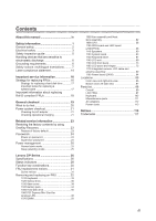
operational charging 21 Related service information Lenovo Z/P Series 26 Specifications 26 Status indicators 28 Function key combinations 30 FRU replacement notices 31 Screw notices 31 Removing and replacing an FRU 32 1010 Keyboard 33 1020 Optical drive 36 1030 Base cover 39 1040 Battery - Lenovo IdeaPad Z400 Touch | Hardware Maintenance Manual - Page 4
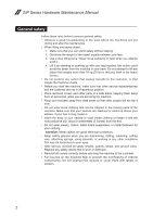
required for servicing computers. •• The product-specific section includes service, reference, and product-specific parts information. Important: This manual is intended only for trained servicers who are familiar with Lenovo products. Use this manual to troubleshoot problems effectively. Before - Lenovo IdeaPad Z400 Touch | Hardware Maintenance Manual - Page 5
the following safety information that you need to get familiar with before you service an Lenovo Z/P Series computer: •• "General safety" on page 2 •• "Electrical safety" on page 3 •• "Safety inspection guide" on page 5 •• "Handling devices that are sensitive to electrostatic discharge" on page - Lenovo IdeaPad Z400 Touch | Hardware Maintenance Manual - Page 6
Manual General a safe place, keeping them away from all personnel, while you are servicing the machine. •• Keep your toolcase away from walk areas so that other clothing or fasten it with the nonconductive clip, about 8 centimeters (3 inches) from the end. •• Do not wear jewelry, chains, metal-frame - Lenovo IdeaPad Z400 Touch | Hardware Maintenance Manual - Page 7
observing the above rule, you may prevent a current from passing through your body. - When using testers, set the controls correctly and use the approved special safety precautions when you work with very high voltages; instructions for these precautions are in the safety sections of maintenance - Lenovo IdeaPad Z400 Touch | Hardware Maintenance Manual - Page 8
Manual •• Always look carefully for possible hazards in your work area. Examples of these hazards are moist floors, nongrounded power extension cables, power surges, and missing safety grounds. •• Do not touch such touching can cause personal injury and machine damage. •• Do not service the - Lenovo IdeaPad Z400 Touch | Hardware Maintenance Manual - Page 9
users and service personnel from injury. This guide addresses only broken, or sharp edges). 2. Turn off the computer. Disconnect the power cord. 3. Check the power batteries. 5. Remove the cover. 6. Check for any obvious non-Lenovo alterations. Use good judgment as to the safety of any non-Lenovo - Lenovo IdeaPad Z400 Touch | Hardware Maintenance Manual - Page 10
a grounded wrist strap against your skin to eliminate static on your body. •• Prevent the part from touching your clothing. Most clothing is insulative and retains a charge even when you are wearing a wrist strap. •• Use the black side of a grounded work mat to provide a static-free work surface - Lenovo IdeaPad Z400 Touch | Hardware Maintenance Manual - Page 11
translations The safety notices in this section are provided in English, French, German, Hebrew, Italian, Japanese, and Spanish. Safety notice 1 Before the computer is powered on after FRU replacement, make sure all screws, springs, and other small parts are in place and are not left loose inside - Lenovo IdeaPad Z400 Touch | Hardware Maintenance Manual - Page 12
Z/P Series Hardware Maintenance Manual Safety notice 2 DANGER Some standby batteries contain a small amount of nickel and cadmium. Do not disassemble a standby battery, recharge it, throw it into fire or water, or shortcircuit it. Dispose of the battery as required by local ordinances or regulations - Lenovo IdeaPad Z400 Touch | Hardware Maintenance Manual - Page 13
, veillez à n'utiliser que les modèles cités dans la liste de pièces détachées adéquate. En effet, une batterie inappropriée risque de prendre feu ou d'exploser. Akkus enthalten geringe Mengen von Nickel. Sie dürfen nicht zerlegt, wiederaufgeladen, kurzgeschlossen, oder Feuer oder Wasser ausgesetzt - Lenovo IdeaPad Z400 Touch | Hardware Maintenance Manual - Page 14
Hardware Maintenance Manual Safety notice 4 DANGER The lithium battery can cause a fire, an explosion, or a severe burn. Do not recharge it, remove its polarized connector, disassemble it, heat it above 100°C (212°F), incinerate it, or expose its cell contents to water. Dispose of the battery as - Lenovo IdeaPad Z400 Touch | Hardware Maintenance Manual - Page 15
or on your hands, immediately wash the affected areas with water at least for 15 minutes. Seek medical care if any symptoms caused by the fluid are present Glas und kann zerbrechen, wenn er unsachgemäß behandelt wird oder der Computer auf den Boden fällt. Wenn der Bildschirm beschädigt ist und die - Lenovo IdeaPad Z400 Touch | Hardware Maintenance Manual - Page 16
Z/P Series Hardware Maintenance Manual Safety notice 6 DANGER To avoid shock, do not remove the plastic abgeben, um brennbare Materialien zu entzünden oder Verletzungen bei Personen hervorzurufen. Sebbene le batterie di alimentazione siano a basso voltaggio, una batteria in corto circuito o a massa - Lenovo IdeaPad Z400 Touch | Hardware Maintenance Manual - Page 17
Safety information Safety notice 8 DANGER Before removing any FRU, turn off the computer, unplug all power cords from electrical outlets, remove the battery pack, and then disconnect any interconnecting cables. Avant de retirer une unité remplaçable en clientèle, mettez le système hors tension, dé - Lenovo IdeaPad Z400 Touch | Hardware Maintenance Manual - Page 18
Z/P Series Hardware Maintenance Manual Laser compliance statement Some models of Lenovo computer are equipped from the factory in the U.S. to conform to the requirements of the Department of Health and Human Services 21 Code of Federal Regulations (DHHS 21 CFR) Subchapter J for Class 1 laser - Lenovo IdeaPad Z400 Touch | Hardware Maintenance Manual - Page 19
visible and invisible laser radiation when open. Do not stare into the beam, do not view directly with optical instruments, and avoid direct exposure to the beam. Radiação por raio laser ao abrir. Não olhe fixo no feixe de con instrumental óptico el haz de luz. Evite la exposición directa al haz. 15 - Lenovo IdeaPad Z400 Touch | Hardware Maintenance Manual - Page 20
the service action. To download software fixes, drivers, and BIOS, follow the steps below: 1. Go to http://consumersupport.lenovo.com/. 2. Enter a serial number or select a product or use Lenovo smart downloading. 3. Select the BIOS/Driver/Applications and download. 4. Follow the directions on - Lenovo IdeaPad Z400 Touch | Hardware Maintenance Manual - Page 21
the following strategy to prevent unnecessary expense for replacing and servicing FRUs: •• If you are instructed to replace an FRU, but the replacement does not solve the problem, reinstall the original FRU before you continue. •• Some computers have both a processor board and a system board. If you - Lenovo IdeaPad Z400 Touch | Hardware Maintenance Manual - Page 22
Manual Important information about replacing RoHS compliant FRUs RoHS, The Restriction of Hazardous Substances in Electrical and Electronic Equipment Directive the implementation date and expects its suppliers to be ready to support Lenovo's requirements and schedule in the EU. Products sold in 2005 - Lenovo IdeaPad Z400 Touch | Hardware Maintenance Manual - Page 23
important notes: Important notes: • Only certified trained personnel can service the computer. • Before replacing any FRU, read the entire page on electrostatic discharge, or software errors. Consider replacing an FRU only when a problem recurs. If you suspect that an FRU is defective, clear the - Lenovo IdeaPad Z400 Touch | Hardware Maintenance Manual - Page 24
problems with the computer, computer unusable) •• Sticky keys caused by spilling a liquid onto the keyboard •• Use of an incorrect AC adapter on laptop products The following symptoms might indicate damage caused by nonwarranted activities: •• Missing parts might be a symptom of unauthorized service - Lenovo IdeaPad Z400 Touch | Hardware Maintenance Manual - Page 25
board. •• If the problem continues, go to "Lenovo Z/P Series" on page 26. Note: Noise from the AC adapter does not always indicate a defect. Checking operational charging To check whether the battery charges properly during operation, use a discharged battery pack or a battery pack that has less - Lenovo IdeaPad Z400 Touch | Hardware Maintenance Manual - Page 26
Maintenance Manual Perform operational charging. If the battery status indicator or icon does not light on, remove the battery pack and let it return to room temperature. Reinstall the battery pack. If the charge indicator or icon is still off, replace the battery pack. If the charge indicator - Lenovo IdeaPad Z400 Touch | Hardware Maintenance Manual - Page 27
service information Related service computer includes a hidden partition when it is shipped. If you need to restore the system to the point of your first boot up, just enter Lenovo OneKey Recovery System and run System Recovery. For details of OneKey Recovery System, see the User Guide for Lenovo - Lenovo IdeaPad Z400 Touch | Hardware Maintenance Manual - Page 28
Manual When you use the recovery discs to boot your computer As many as two passwords may be needed for any Lenovo computer: the power-on password (POP) and the supervisor password configuration. Attention: If the SVP has been forgotten and cannot be made available to the servicer, there is no service - Lenovo IdeaPad Z400 Touch | Hardware Maintenance Manual - Page 29
service information Power management Note: Power management modes are not supported for APM operating system. To reduce power consumption, the computer that time. •• If the battery indicator is amber, indicating that the battery power is low. To cause the computer to return from sleep (standby) - Lenovo IdeaPad Z400 Touch | Hardware Maintenance Manual - Page 30
Z/P Series Hardware Maintenance Manual Lenovo Z/P Series This chapter presents the following product-specific service references and product-specific parts information: •• "Specifications" on page 26 •• "Status indicators" on page 28 •• "Function key combinations" on page 30 •• "FRU replacement - Lenovo IdeaPad Z400 Touch | Hardware Maintenance Manual - Page 31
Lenovo Z/P Series Table 1. Specifications (continued) Feature I/O port Audio Ethernet (on the system board) PCI Express Mini Card slot Bluetooth wireless Keyboard Touch pad Integrated camera Battery Wifi, BT 4.0 option • 6 Row, ISO Full Size Keyboard • Multi-touch type • 720P HD or 0.3 Mega • 4 - Lenovo IdeaPad Z400 Touch | Hardware Maintenance Manual - Page 32
Z/P Series Hardware Maintenance Manual Status indicators The system status indicators below show the computer status: Z400 1 2 28 - Lenovo IdeaPad Z400 Touch | Hardware Maintenance Manual - Page 33
Z500/P500 Lenovo Z/P Series 1 2 Table 2. Status indicators Indicator Indicator status On (solid white) Power Blinking Off On (solid white) On (solid amber) Battery Blinking slowly (white) Blinking slowly (amber) Blinking quickly (amber) Charge Status ------Charging Discharging - Lenovo IdeaPad Z400 Touch | Hardware Maintenance Manual - Page 34
Z/P Series Hardware Maintenance Manual Function key combinations The following table shows the function of each off the backlight of the LCD screen. : Toggles the display between the computer and an external device. : Decreases display brightness. : Increases display brightness. 30 - Lenovo IdeaPad Z400 Touch | Hardware Maintenance Manual - Page 35
Loose screws can cause a reliability problem. In the Lenovo computer, this problem is addressed with special nylon-coated Turn an additional 180° after the screw head touches the surface of the logic card: more than 180° (Cross-section) •• Torque driver If you have a torque screwdriver , refer to - Lenovo IdeaPad Z400 Touch | Hardware Maintenance Manual - Page 36
Z/P Series Hardware Maintenance Manual Removing and replacing an FRU This section presents exploded figures with the instructions to indicate how to remove and replace the FRU. Make sure to observe the following general rules: 1. Do not attempt to service any computer unless you have been trained - Lenovo IdeaPad Z400 Touch | Hardware Maintenance Manual - Page 37
Lenovo Z/P Series 1010 Keyboard Figure 1. Removal steps of keyboard Remove the two screws 1. Z400 1 1 Z500/P500 1 1 Step Screw (quantity) 1 M2 × 12 mm, flat-head, nylok-coated (2) (Z400) 1 M2 × 12 mm, flat-head, nylok-coated (2) (Z500/ P500) Color Black Black Torque 1.85+/-0.15 kgf*cm 3.62 - Lenovo IdeaPad Z400 Touch | Hardware Maintenance Manual - Page 38
Z/P Series Hardware Maintenance Manual Figure 1. Removal steps of keyboard (continued) Insert the screwdriver into one of the screw hole on the bottom 2. Then pull the keyboard out of the keyboard bezel 3. Z400 2 3 Z500/P500 2 3 34 - Lenovo IdeaPad Z400 Touch | Hardware Maintenance Manual - Page 39
Lenovo Z/P Series Figure 1. Removal steps of keyboard (continued) Lift the keyboard a little, and then detach the connectors in the direction shown by arrows 4 5. Remove the keyboard in the direction shown by arrow 6. Z400 4 6 5 Z500/P500 4 5 6 4 5 When installing: Make sure that the FPC - Lenovo IdeaPad Z400 Touch | Hardware Maintenance Manual - Page 40
Z/P Series Hardware Maintenance Manual 1020 Optical drive For access, remove this FRU: •• "1010 Keyboard" on page 33 Figure 2. Removal steps of optical drive Remove the screw 1. Z400 1 36 - Lenovo IdeaPad Z400 Touch | Hardware Maintenance Manual - Page 41
Lenovo Z/P Series Figure 2. Removal steps of Optical drive (continued) Z500/P500 1 Step 1 1 Screw (quantity) Color M2.5 × 6 mm, flat-head, nylok-coated (1) (Z400) Black M2.5 × 6 mm, flat-head, nylok-coated (1) (Z500/ Black P500) Torque 3.0+/-0.3 kgf*cm 8.03 kg-cm 37 - Lenovo IdeaPad Z400 Touch | Hardware Maintenance Manual - Page 42
Z/P Series Hardware Maintenance Manual Figure 2. Removal steps of Optical drive (continued) Insert a screwdriver into the screw hole and push the optical drive in the direction shown by arrow 2 . Pull the optical drive out in the direction shown by arrow 3. Z400 2 3 Z500/P500 2 3 38 - Lenovo IdeaPad Z400 Touch | Hardware Maintenance Manual - Page 43
, remove this FRU: •• "1010 Keyboard" on page 33 •• "1020 Optical drive" on page 36 Figure 3. Removal steps of base cover Z400 Remove the four screws 1. 1 1 1 Lenovo Z/P Series Step 1 Screw (quantity) M2.5 × 6 mm, flat-head, nylok-coated (4) Color Torque Black 3.0+/-0.3 kgf*cm 39 - Lenovo IdeaPad Z400 Touch | Hardware Maintenance Manual - Page 44
Z/P Series Hardware Maintenance Manual Figure 3. Removal steps of base cover (continued) Remove the two rubber × 3 mm, flat-head, nylok-coated (3) Color Torque Black 3.0+/-0.3 kgf*cm Black 1.85+/-0.15 kgf*cm Black 1.85+/-0.15 kgf*cm Remove the base cover in the direction shown by arrow 6. 6 40 - Lenovo IdeaPad Z400 Touch | Hardware Maintenance Manual - Page 45
Lenovo Z/P Series Figure 3. Removal steps of base cover (continued) Z500/P500 Remove the five screws 1. 1 1 1 1 Step 1 Screw (quantity) M2.5 × 6 mm, flat-head, nylok-coated (5) Color Black Torque 8.03 kg-cm 41 - Lenovo IdeaPad Z400 Touch | Hardware Maintenance Manual - Page 46
Z/P Series Hardware Maintenance Manual Figure 3. Removal steps of base cover (continued) Open the four rubber feet 2. (4) M2 × 5 mm, flat-head, nylok-coated (3) M2 × 2.5 mm, flat-head, nylok-coated (3) Color Black Black Black Torque 8.03 kg-cm 3.62 kg-cm 3.62 kg-cm Remove the base cover in the - Lenovo IdeaPad Z400 Touch | Hardware Maintenance Manual - Page 47
Lenovo Z/P Series Note: Applying labels to the base cover The new base cover FRU is shipped with a kit containing labels of several kinds. When you replace - Lenovo IdeaPad Z400 Touch | Hardware Maintenance Manual - Page 48
specified in the parts list for your computer. Any other battery could ignite or explode. Figure 4. Removal steps of battery pack Detach the battery pack connector in the direction shown by arrow 1, remove the two screws 2. Z400 2 2 1 Z500/P500 2 2 1 Step Screw (quantity) 2 M2.5 × 3 mm, flat - Lenovo IdeaPad Z400 Touch | Hardware Maintenance Manual - Page 49
Lenovo Z/P Series Figure 4. Removal steps of battery pack (continued) Remove the battery pack in the direction shown by arrow 3. Z400 3 Z500/P500 3 When installing: Make sure the battery pack connector is attached firmly. 45 - Lenovo IdeaPad Z400 Touch | Hardware Maintenance Manual - Page 50
Manual 1050 Hard disk drive For access, remove these FRUs in order: •• "1010 Keyboard" on page 33 •• "1020 Optical drive" on page 36 •• "1030 Base cover" on page 39 •• "1040 Battery four screws 1. Z400 1 1 1 Z500/P500 1 1 1 Step Screw (quantity) 1 M2.5 × 3 mm, flat-head - Lenovo IdeaPad Z400 Touch | Hardware Maintenance Manual - Page 51
Lenovo Z/P Series Figure 5. Removal steps of hard disk drive (continued) Detach the HDD connector in the direction shown by arrow 2. Remove the hard disk drive from the slot in the direction shown by arrow 3. Z400 3 2 Z500/P500 3 2 When installing: Make sure that the HDD connector is attached - Lenovo IdeaPad Z400 Touch | Hardware Maintenance Manual - Page 52
page 36 •• "1030 Base cover" on page 39 •• "1040 Battery pack" on page 44 Figure 6. Removal steps of PCI Express Mini Card for wireless LAN Disconnect the two wireless LAN cables (black, white) 1, and then remove the screw 2. Z400 2 1 Z500/P500 2 1 In step 1, unplug the jacks by using the removal - Lenovo IdeaPad Z400 Touch | Hardware Maintenance Manual - Page 53
Lenovo Z/P Series Figure 6. Removal steps of PCI Express Mini Card for wireless LAN (continued) Remove the card in the direction shown by arrow 3. Z400 3 Z500/P500 3 When installing: •• In models with a wireless LAN card that has two antenna connectors, plug the black cable (1st) (MAIN) into the - Lenovo IdeaPad Z400 Touch | Hardware Maintenance Manual - Page 54
page 33 •• "1020 Optical drive" on page 36 •• "1030 Base cover" on page 39 •• "1040 Battery pack" on page 44 Figure 7. Removal steps of DIMM Release the two latches on both edges of the socket at the same time in the direction shown by arrows 1, and then unplug the DIMM in the - Lenovo IdeaPad Z400 Touch | Hardware Maintenance Manual - Page 55
Lenovo Z/P Series Figure 7. Removal steps of DIMM (continued) Z500/P500 1 1 2 When installing: Insert the notched end of the DIMM into the socket. Push the DIMM firmly, and pivot it until it snaps into the place. Make sure that it is firmly fixed in the slot and difficult to be moved. 51 - Lenovo IdeaPad Z400 Touch | Hardware Maintenance Manual - Page 56
in the direction shown by arrow 1 , and then remove a total of six screws (three 2, two 3 and one 4). Z400 3 2 2 3 4 1 Step Screw (quantity) 2 M2 × 3.2, flat-head, nylok-coated (3) 3 M2 × 3, flat-head, nylok-coated (2) 4 M2.5 × 6, flat-head, nylok-coated (1) Color Torque Black 1.85+/-0.15 kgf - Lenovo IdeaPad Z400 Touch | Hardware Maintenance Manual - Page 57
Lenovo Z/P Series Figure 8. Removal steps of fan assembly and heat sink assembly (continued) Z500/P500 3 3 2 2 4 1 Step 2 3 4 Screw (quantity) M2 × 3.2, flat-head, nylok-coated (3) M2 × 2.5, flat-head, nylok-coated (2) M2.5 × 6, flat-head, nylok-coated (1) Color Black Black Black Torque 3.62 - Lenovo IdeaPad Z400 Touch | Hardware Maintenance Manual - Page 58
Z/P Series Hardware Maintenance Manual Figure 8. Removal steps of fan assembly and heat sink assembly (continued) Lift the fan assembly and heat sink assembly in the direction shown by arrow 5. Be careful not to damage the connector. Z400 5 Z500/P500 5 Attention: Do not handle the heat sink assembly - Lenovo IdeaPad Z400 Touch | Hardware Maintenance Manual - Page 59
assembly (continued) Z400 Z500/P500 a b a b When installing: Before you attach the fan assembly to the computer, apply thermal grease, at an amount of 0.2 grams, to the a b part shown in the figure above. Either too much or too less grease application can cause a thermal problem due to imperfect - Lenovo IdeaPad Z400 Touch | Hardware Maintenance Manual - Page 60
Manual 1090 CPU For access, remove these FRUs in order: •• "1010 Keyboard" on page 33 •• "1020 Optical drive" on page 36 •• "1030 Base cover" on page 39 •• "1040 Battery service the CPU, avoid any kind of rough handling. Figure 9. Removal steps of CPU Rotate the head of the screw in the direction - Lenovo IdeaPad Z400 Touch | Hardware Maintenance Manual - Page 61
Figure 9. Removal steps of CPU (continued) Z500/P500 Lenovo Z/P Series 1 a b 2 When installing: Place the CPU on the CPU socket in the direction shown by arrow a , and then rotate the head of the screw in the direction shown by arrow b to secure the CPU. 57 - Lenovo IdeaPad Z400 Touch | Hardware Maintenance Manual - Page 62
Z/P Series Hardware Maintenance Manual 1100 ODD board and LED board (Z500/P500) For access, remove these FRUs in order: •• "1010 Keyboard" on page 33 •• "1020 Optical drive" on page 36 •• "1030 Base cover" on page 39 •• "1040 Battery pack" on page 44 •• "1050 Hard disk drive" on page 46 •• "1060 - Lenovo IdeaPad Z400 Touch | Hardware Maintenance Manual - Page 63
Lenovo Z/P Series Figure 10. Removal steps of ODD board and LED board (continued) Remove the two boards in the direction shown by arrows 5. 5 5 When installing: Make sure that the two FPC connectors are attached firmly. 59 - Lenovo IdeaPad Z400 Touch | Hardware Maintenance Manual - Page 64
Manual 1110 Speakers For access, remove these FRUs in order: •• "1010 Keyboard" on page 33 •• "1020 Optical drive" on page 36 •• "1030 Base cover" on page 39 •• "1040 Battery board (Z500/P500)" on page 58 Figure 11. Removal steps of speakers Detach the speakers connector in the direction shown by - Lenovo IdeaPad Z400 Touch | Hardware Maintenance Manual - Page 65
Lenovo Z/P Series Figure 11. Removal steps of speakers (continued) Z500/P500 2 2 2 1 Step 2 Screw (quantity) M2 × 5.7, flat-head, nylok-coated (4) Color Black Torque 8.03 kg-cm 61 - Lenovo IdeaPad Z400 Touch | Hardware Maintenance Manual - Page 66
Z/P Series Hardware Maintenance Manual Figure 11. Removal steps of speakers (continued) Remove the speakers 3. Z400 3 3 Z500/P500 3 3 When installing: Make sure that the speakers connector is attached firmly. 62 - Lenovo IdeaPad Z400 Touch | Hardware Maintenance Manual - Page 67
Lenovo •• "1020 Optical drive" on page 36 •• "1030 Base cover" on page 39 •• "1040 Battery pack" on page 44 •• "1050 Hard disk drive" on page 46 •• "1060 PCI Express Mini assembly" on page 52 •• "1100 ODD board and LED board (Z500/P500)" on page 58 •• "1110 Speakers" on page 60 Figure 12. Removal - Lenovo IdeaPad Z400 Touch | Hardware Maintenance Manual - Page 68
Z/P Series Hardware Maintenance Manual Figure 12. Removal steps of system board (continued) Z500/P500 1 2 1 2 Detach the power connector and LCD connector in the direction shown by arrows 3. Remove a total of six screws (four 4, one 5 and one 6) from the bottom. Z400 3 4 4 5 3 6 64 - Lenovo IdeaPad Z400 Touch | Hardware Maintenance Manual - Page 69
Lenovo Z/P Series Figure 12. Removal steps of system board (continued) Z500/P500 3 4 5 3 6 When installing: Make sure that the power connector is attached firmly. Step 4 4 5 5 6 6 Screw (quantity) Color M2.5 × 3 mm, flat-head, nylok-coated (4) Black (Z400) M2.5 × 3 mm, flat-head, nylok- - Lenovo IdeaPad Z400 Touch | Hardware Maintenance Manual - Page 70
Z/P Series Hardware Maintenance Manual Figure 12. Removal steps of system board (continued) Remove the RJ-45 door in the direction shown by arrow 7. Remove the system board in the direction shown by arrow 8. Z400 8 7 Z500/P500 8 7 66 - Lenovo IdeaPad Z400 Touch | Hardware Maintenance Manual - Page 71
" on page 63 Figure 13. Removal steps of keyboard bezel Z400 Remove the two screws 1. 1 Step Screw (quantity) 1 M2.5 × 3 mm, flat-head, nylok-coated (2) Color Black Torque 3.0+/-0.3 kgf*cm Remove the USB board and DC-in jack in the direction shown by arrows 2. 2 2 67 - Lenovo IdeaPad Z400 Touch | Hardware Maintenance Manual - Page 72
Series Hardware Maintenance Manual Figure 13. Removal steps of keyboard bezel (continued) Z500/P500 Remove a total of three screws (two 1 and one 2) . 1 2 Step 1 2 Screw (quantity) M2.5 × 3 mm, flat-head, nylok-coated (2) M2.5 × 6 mm, flat-head, nylok-coated (1) Color Black Black Torque 8.03 kg - Lenovo IdeaPad Z400 Touch | Hardware Maintenance Manual - Page 73
Lenovo Z/P Series 1140 LCD unit For access, remove these FRUs in order: •• "1010 Keyboard" on page 33 •• "1020 Optical drive" on page 36 •• "1030 Base cover" on page 39 •• "1040 Battery " on page 67 Attention: • Z400 Touch, Z500 Touch and P400 Touch use the touchscreen module which cannot be - Lenovo IdeaPad Z400 Touch | Hardware Maintenance Manual - Page 74
Z/P Series Hardware Maintenance Manual Figure 14. Removal steps of LCD unit Z500/P500 Remove the five screws 1. 1 1 Step 1 1' Screw (quantity) M2.5 × 6 mm, flat-head, nylok-coated (5) M2 × 2 mm, flat-head, nylok-coated (1) (Z400) Color Torque Black 8.03 kg-cm Black 1.85+/-0.15 kgf*cm 70 - Lenovo IdeaPad Z400 Touch | Hardware Maintenance Manual - Page 75
Lenovo Z/P Series Figure 14. Removal steps of LCD unit (continued) Release the LCD cable from the cable guides in the direction shown by arrows 2. Then lift the LCD hinge in the direction shown by arrow 3. Z400 3 2 2 2 3 Z500/P500 3 2 2 2 3 When installing: •• Route the antenna cables - Lenovo IdeaPad Z400 Touch | Hardware Maintenance Manual - Page 76
Z/P Series Hardware Maintenance Manual Figure 14. Removal steps of LCD unit (continued) Remove the keyboard bezel from the LCD unit in the direction shown by arrows 4. Z400 4 Z500/P500 4 72 - Lenovo IdeaPad Z400 Touch | Hardware Maintenance Manual - Page 77
ODD board and LED board (Z500/P500)" on page 58 •• "1110 Speakers" on page 60 •• "1120 System board" on page 63 •• "1130 Keyboard bezel" on page 67 •• "1140 LCD unit" on page 69 Figure 15. Removal steps of LCD front bezel Remove the LCD front bezel in the direction shown by arrows 1. Z400 - Lenovo IdeaPad Z400 Touch | Hardware Maintenance Manual - Page 78
Z/P Series Hardware Maintenance Manual Figure 15. Removal steps of LCD front bezel Z500/P500 1 1 1 1 74 - Lenovo IdeaPad Z400 Touch | Hardware Maintenance Manual - Page 79
page 39 •• "1040 Battery pack" on page 44 •• "1050 Hard disk drive" on page 46 •• "1060 PCI Express Mini Card for wireless LAN" on page 48 •• "1070 DIMM" on page 50 •• "1080 Fan assembly and Heat Sink assembly" on page 52 •• "1100 ODD board and LED board (Z500/P500)" on page 58 - Lenovo IdeaPad Z400 Touch | Hardware Maintenance Manual - Page 80
quantity) M2 × 3 mm, flat-head, nylok-coated (4) (Z400) M2 × 2.5 mm, flat-head, nylok-coated (4) (Z500/P500) Color Black Black Torque 1.85+/-0.15 kgf*cm 3.62 kg-cm Lift the LCD panel a little 2. Peel off the adhesive tape and detach the connector in the direction shown by arrow 3. Z400 2 3 76 - Lenovo IdeaPad Z400 Touch | Hardware Maintenance Manual - Page 81
Lenovo Z/P Series Figure 16. Removal steps of LCD panel and hinges (continued) Z500/P500 2 3 When installing: Make sure that the metal connector is attached firmly. Remove the LCD panel 4. Z400 4 77 - Lenovo IdeaPad Z400 Touch | Hardware Maintenance Manual - Page 82
Z/P Series Hardware Maintenance Manual Figure 16. Removal steps of LCD panel and hinges (continued) Z500/P500 4 Z400 Remove a total of eight screws (two 5 and six 6). Then release the two hinges in the direction shown by arrows 7. 7 6 5 6 5 7 78 - Lenovo IdeaPad Z400 Touch | Hardware Maintenance Manual - Page 83
two hinges in the direction shown by arrows 7. 5 7 6 6 5 7 Step Screw (quantity) Color 5 M2 × 2.5 mm, flat-head, nylok-coated (2) Black 6 M2 × 3 mm, flat-head, nylok-coated (6) (Z400) Black 6 M2 × 3 mm, flat-head, nylok-coated (8) Black (Z500/P500) Torque 3.62 kg-cm 1.85+/-0.15 kgf*cm 8.03 - Lenovo IdeaPad Z400 Touch | Hardware Maintenance Manual - Page 84
Manual 1170 Integrated camera, LCD cable and antenna assembly For access, remove these FRUs in order: •• "1010 Keyboard" on page 33 •• "1020 Optical drive" on page 36 •• "1030 Base cover" on page 39 •• "1040 Battery . Detach the integrated camera connector in the direction shown by arow 1. Z400 1 80 - Lenovo IdeaPad Z400 Touch | Hardware Maintenance Manual - Page 85
of integrated camera, LCD cable and antenna assembly (continued) Z500/P500 1 When installing: Stick the integrated camera to the top center of the LCD cover and ajust the placement of it to make sure the connector is attached firmly. Remove the camera in the direction shown by arrow 2. Z400 2 81 - Lenovo IdeaPad Z400 Touch | Hardware Maintenance Manual - Page 86
Z/P Series Hardware Maintenance Manual Figure 17. Removal steps of integrated camera, LCD cable and antenna assembly (continued) Z500/P500 2 Remove the LCD cable and antenna assembly in the direction shown by arrow 3. Z400 3 3 3 82 - Lenovo IdeaPad Z400 Touch | Hardware Maintenance Manual - Page 87
Lenovo Z/P Series Figure 17. Removal steps of integrated camera, LCD cable and antenna assembly (continued) Z500/P500 3 3 83 - Lenovo IdeaPad Z400 Touch | Hardware Maintenance Manual - Page 88
Z/P Series Hardware Maintenance Manual 1180 Power board (Z400) For access, remove these FRUs in order: •• "1010 Keyboard" on page 33 •• "1020 Optical drive" on page 36 •• "1030 Base cover" on page 39 •• "1040 Battery pack" on page 44 •• "1050 Hard disk drive" on page 46 •• "1060 PCI Express Mini - Lenovo IdeaPad Z400 Touch | Hardware Maintenance Manual - Page 89
Lenovo Z/P Series Locations Front view and right-side view 1 Integrated camera 2 Built-in microphone 3 Wireless LAN antennas 4 Computer display 5 Power button 6 Touchpad 7 System status indicators Note: For the description of each indicator, see "Status indicators" on page 28. 8 Combo audio jack 9 - Lenovo IdeaPad Z400 Touch | Hardware Maintenance Manual - Page 90
Z/P Series Hardware Maintenance Manual Z500/P500 4 2 3 1 3 5 6 7 9 8 11 10 86 - Lenovo IdeaPad Z400 Touch | Hardware Maintenance Manual - Page 91
Bottom and Left-side view 1 Speakers 2 Memory card slot 3 USB port 4 HDMI port 5 RJ-45 port 6 VGA port 7 Fan louvers 8 Novo button 9 AC power adapter jack Z400 1 Z500/P500 1 1 Lenovo Z/P Series 9 8 7 6 5 4 3 2 9 8 7 6 5 4 3 2 87 - Lenovo IdeaPad Z400 Touch | Hardware Maintenance Manual - Page 92
presents the following service parts: •• "Overall" on page 89 •• "LCD FRUs" on page 97 •• "Keyboard" on page 102 •• "Miscellaneous parts" on page 111 •• "AC adapters" on page 112 •• "Power cords" on page 113 Notes: • Each FRU is available for all types or models, unless specific types or models - Lenovo IdeaPad Z400 Touch | Hardware Maintenance Manual - Page 93
Overall Z400 1 19 f 5 e 7 9 10 12 14 17 Lenovo Z/P Series 2 3 a 8 4 b 6 13 16 c 18 d 89 - Lenovo IdeaPad Z400 Touch | Hardware Maintenance Manual - Page 94
Z/P Series Hardware Maintenance Manual Z500/P500 1 f 5 7 9 10 12 14 e 17 90 2 3 4 a 8 6 b 11 13 15 16 c 18 d - Lenovo IdeaPad Z400 Touch | Hardware Maintenance Manual - Page 95
"LCD FRUs" on page 97.) 1 Touch module for Z400 Touch, GZE LEG-04M-1D 73044074 GFF Na SY Z400 TSP 1 Touch module for Z400 Touch, OFO MCF-140-0650 73044075 N GFF Na SY Z400 TSP 2 Keyboard (see "Keyboard" on page 102.) 3 VIWP1 Upper Case 90202307 4 Battery, 4S1P, 4cell, 48Wh, sanyo, Z400Z500 - Lenovo IdeaPad Z400 Touch | Hardware Maintenance Manual - Page 96
Manual Table 5. Parts list-Overall (continued) No. FRU FRU no. CRU ID. 6 Platform, Chief River platform 35w, Intel I5-3360M 102500297 2.8G L1 3M 2cPGA 6 Platform, Chief River platform 35w, Intel I5-3320M 102500299 2.6G L1 3M 2cPGA 6 Platform, Chief River platform 35w, Intel I5-3210M - Lenovo IdeaPad Z400 Touch | Hardware Maintenance Manual - Page 97
Lenovo Z/P Series No. FRU FRU no. CRU ID. 12 RAM, Nanya, NT4GC64B8HG0NS-DI DDR3 1600 11201042 4GB 12 RAM, Samsung, M471B1G73BH0-CK0 DDR3 1600 11200342 8GB - Lenovo IdeaPad Z400 Touch | Hardware Maintenance Manual - Page 98
GFF Na SY P400 TSP 1 Touch module for Z500 Touch, GZE LEG-07M-1D 73044811 N GFF Na SY ZP500 TSP 1 Touch module for Z500 Touch, OFO MCF-156-0751 73044812 GFF Na At ZP500 TSP 2 Keyboard (see "Keyboard" on page 102.) 3 VIWZ2 Upper Case 90202121 4 Battery, 4S1P, 4cell,48Wh, sanyo, Z400Z500 - Lenovo IdeaPad Z400 Touch | Hardware Maintenance Manual - Page 99
Lenovo Z/P Series Table 6. Parts list-Overall (Z500/P500) (continued) No. FRU FRU no. CRU ID. 6 8A5SH Slim Tray DVD Rambo ODD N 8 Optical Disk Driver, 9.5mm Tray in BD Rambo, PSN 25209259 UJ262 9.5mm Tray in BD Rambo 8 Optical Disk Driver, 9.5mm Tray in BD Rambo, HLDS 25209260 BU10N 9. - Lenovo IdeaPad Z400 Touch | Hardware Maintenance Manual - Page 100
Z/P Series Hardware Maintenance Manual Table 6. Parts list-Overall (Z500/P500) (continued) No. FRU FRU 1 x 1 B G N + B T 4 . 0 , L i t e o n W B 2 2 5 20200224 1x1BGN+BT4.0 HMC 15 VIWZ2 LED Board W/Cable 90001774 16 Hard disk drive, 500G 5400rpm, Samsung M8, 16200210 ST500LM012 5.4K RPM 9.5mm - Lenovo IdeaPad Z400 Touch | Hardware Maintenance Manual - Page 101
Lenovo Z/P Series LCD FRUs In Lenovo Z400/Z500/P500, there are following types of LCDs. •• "14-in. HD TFT" 1 2 3 4 5 6 7 97 - Lenovo IdeaPad Z400 Touch | Hardware Maintenance Manual - Page 102
Z/P Series Hardware Maintenance Manual •• "15.6-in. HD TFT" 1 2 3 4 5 6 7 98 - Lenovo IdeaPad Z400 Touch | Hardware Maintenance Manual - Page 103
Lenovo Z/P Series 14-in. HD TFT Table 7. Parts list-14-in. HD TFT No. FRU FRU no. CRU ID. 1 VIWP1 LCD Bezel 90202316 2 VIWP1 LCD Hinge L+R - Lenovo IdeaPad Z400 Touch | Hardware Maintenance Manual - Page 104
Z/P Series Hardware Maintenance Manual 100 15.6-in. HD TFT Table 8. Parts list-15.6-in. HD TFT No. FRU FRU no. CRU LCD 4 Camera, HD(For Z500&P500), BIS BN6R18VVQ HD NB camera 73042534 N 4 Camera, HD(For Z500&P500), CCY CKFC113 HD NB 73042535 camera 4 Camera, HD(For Z500&P500), AWA AM-1H047 - Lenovo IdeaPad Z400 Touch | Hardware Maintenance Manual - Page 105
Lenovo Z/P Series Table 8. Parts list-15.6-in. HD TFT (continued) No. FRU FRU no. CRU ID. 4 Camera, 0.3M(For P500), AWA AM-VS058 0.3M NB camera 61dB 73044060 4 Camera, 0.3M(For - Lenovo IdeaPad Z400 Touch | Hardware Maintenance Manual - Page 106
Z/P Series Hardware Maintenance Manual Keyboard Table 9. Parts list-Keyboard (Z400) Language Chicony Z400 (win8) Sunrex English U.K. English Italian Spanish Turkish Thai Portuguese Latin Canadian Bilingual (En+Fr) Korean Traditional - Lenovo IdeaPad Z400 Touch | Hardware Maintenance Manual - Page 107
Lenovo Z/P Series Table 9. Parts list-Keyboard (Z400) (continued) Language Sunrex (continued) Z400 (win8) (continued) Darfon Arabic Brazilian Dutch Greek Hebrew Hungarian Nordic Belgian Icelandic Slovenian Swiss - Lenovo IdeaPad Z400 Touch | Hardware Maintenance Manual - Page 108
Z/P Series Hardware Maintenance Manual Table 9. Parts list-Keyboard (Z400) (continued) Language Chicony (with backlight) Z400 (win8) (continued) Darfon (with backlight) English U.K. English Italian Spanish Turkish Thai Portuguese Latin Canadian - Lenovo IdeaPad Z400 Touch | Hardware Maintenance Manual - Page 109
Lenovo Z/P Series Table 9. Parts list-Keyboard (Z400) (continued) Language Z400 (win8) Darfon (with backlight) (continued) (continued) Japanese Dutch Greek Hebrew Hungarian Nordic Belgian Icelandic Slovenian Swiss - Lenovo IdeaPad Z400 Touch | Hardware Maintenance Manual - Page 110
Z/P Series Hardware Maintenance Manual 106 Table 10. Parts list-Keyboard (Z500/P500) Language Chicony Z500 (win8) Darfon Arabic Belgian Brazilian Bulgarian Canadian Bilingual (En+Fr) Czech&Slovak Dutch French German Greek Hebrew Hungarian Icelandic Indic Italian Japanese Korean Latin Nordic - Lenovo IdeaPad Z400 Touch | Hardware Maintenance Manual - Page 111
Lenovo Z/P Series Table 10. Parts list-Keyboard (Z500/P500) (continued) Language Darfon (continued) Z500 (win8) (continued) Darfon (with backlight) Japanese Korean Latin Nordic Portuguese Russian Slovenian Spanish Swiss Traditional Chinese Thai Turkish U.K. English English US international Arabic - Lenovo IdeaPad Z400 Touch | Hardware Maintenance Manual - Page 112
Z/P Series Hardware Maintenance Manual 108 Table 10. Parts list-Keyboard (Z500/P500) (continued) Language OKI (with backlight) Z500 (win8) (continued) Sunrex Arabic Belgian Brazilian Bulgarian Canadian Bilingual (En+Fr) Czech&Slovak Dutch French German Greek Hebrew Hungarian Icelandic Indic - Lenovo IdeaPad Z400 Touch | Hardware Maintenance Manual - Page 113
Lenovo Z/P Series Table 10. Parts list-Keyboard (Z500/P500) (continued) Language Sunrex (continued) Z500 (win8) (continued) Sunrex (with backlight) Nordic Portuguese Russian Slovenian Spanish Swiss Traditional Chinese Thai Turkish U.K. English English US international Arabic Belgian Brazilian - Lenovo IdeaPad Z400 Touch | Hardware Maintenance Manual - Page 114
Z/P Series Hardware Maintenance Manual Table 10. Parts list-Keyboard (Z500/P500) (continued) Language Darfon P500 (win8) Darfon (with backlight) Chicony OKI (with backlight) Sunrex Sunrex (with backlight) Canadian Bilingual (En+Fr) English Canadian Bilingual (En+ - Lenovo IdeaPad Z400 Touch | Hardware Maintenance Manual - Page 115
Lenovo Z/P Series Miscellaneous parts Z400 Table 11. Parts list-Miscellaneous parts (Z400) FRU System are references to the exploded view in "Overall" on page 89 . Z500/P500 Table 12. Parts list-Miscellaneous parts (Z500/P500) FRU System miscellaneous parts: • (a) VIWZ2 ODD Bracket • (b) - Lenovo IdeaPad Z400 Touch | Hardware Maintenance Manual - Page 116
Z/P Series Hardware Maintenance Manual AC adapters Table 13. Parts list-3-pin AC adapters FRU 65W, Delta ADP-65KH BD 20V/3.25A Adapter 65W, Liteon PA-1650-56LC Adapter 65W, - Lenovo IdeaPad Z400 Touch | Hardware Maintenance Manual - Page 117
Z/P Series Power cords A Lenovo power cord for a specific country or region is usually available only in that country or region: Table 14. Parts list-3-pin power cords Region CCC • LINETEK PC323+RVV300/300+ - Lenovo IdeaPad Z400 Touch | Hardware Maintenance Manual - Page 118
Z/P Series Hardware Maintenance Manual 114 Table 14. Parts list-3-pin power cords (continued) Region Israel • Longwell LP-41+H03VV-F+LS-18 1m UL • Longwell LP-30B+SPT-2 18AWG+LS- - Lenovo IdeaPad Z400 Touch | Hardware Maintenance Manual - Page 119
Lenovo Z/P Series Table 14. Parts list-3-pin power cords (continued) Region Argentina • VOLEX VA2073+H03VV-F+VAC5S 1m Brazil • VOLEX CH10S3+H03VV-F+VAC5S 1m Israel • VOLEX SI16S3+ - Lenovo IdeaPad Z400 Touch | Hardware Maintenance Manual - Page 120
the operation of any other product, program, or service. Lenovo may have patents or pending patent applications covering support applications where malfunction may result in injury or death to persons. The information contained in this document does not affect or change Lenovo product specifications - Lenovo IdeaPad Z400 Touch | Hardware Maintenance Manual - Page 121
their specific environment. Trademarks The following terms are either registered trademarks or trademarks of Lenovo in the United States and/or other countries: Lenovo® Lenovo logo® IdeaPad® VeriFace both: Intel® Intel® Core™ 2 Duo Other company, product, or service names may be the trademarks or
-
 1
1 -
 2
2 -
 3
3 -
 4
4 -
 5
5 -
 6
6 -
 7
7 -
8
-
9
-
10
-
11
-
12
-
13
-
14
-
15
-
16
-
17
-
18
-
19
-
20
-
21
-
22
-
23
-
24
-
25
-
26
-
27
-
28
-
29
-
30
-
31
-
32
-
33
-
34
-
35
-
36
-
37
-
38
-
39
-
40
-
41
-
42
-
43
-
44
-
45
-
46
-
47
-
48
-
49
-
50
-
51
-
52
-
53
-
54
-
55
-
56
-
57
-
58
-
59
-
60
-
61
-
62
-
63
-
64
-
65
-
66
-
67
-
68
-
69
-
70
-
71
-
72
-
73
-
74
-
75
-
76
-
77
-
78
-
79
-
80
-
81
-
82
-
83
-
84
-
85
-
86
-
87
-
88
-
89
-
90
-
91
-
92
-
93
-
94
-
95
-
96
-
97
-
98
-
99
-
100
-
101
-
102
-
103
-
104
-
105
-
106
-
107
-
108
-
109
-
110
-
111
-
112
-
113
-
114
-
115
-
116
-
117
-
118
-
119
-
120
-
121
 |
 |

Lenovo Z/P Series
Hardware
Maintenance
Manual