Lenovo IdeaPad Z460 Lenovo IdeaPad Z460/Z465 Hardware Maintenance Manual - Page 51
Notes, When installing
 |
View all Lenovo IdeaPad Z460 manuals
Add to My Manuals
Save this manual to your list of manuals |
Page 51 highlights
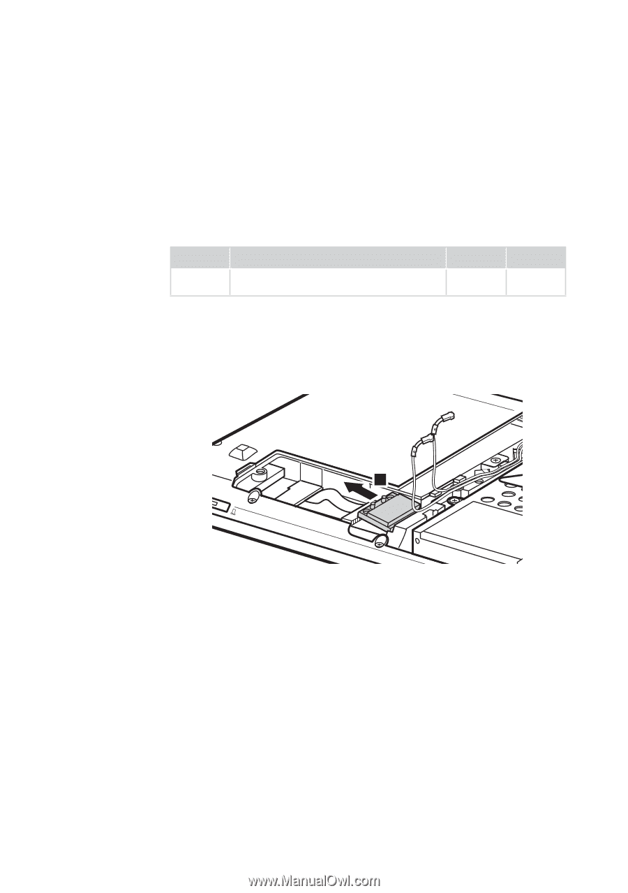
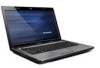
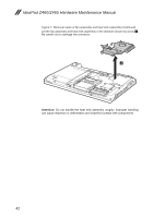
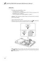
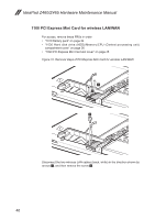
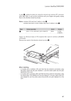
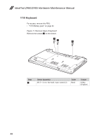
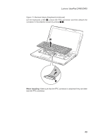
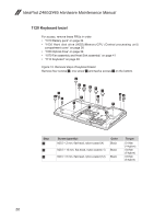
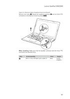
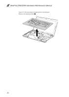
Lenovo IdeaPad Z460/Z465 In step 1, unplug the jacks by using the removal tool antenna RF connector (P/N: 08K7159), or pick up the connectors with your fingers and gently unplug them in the direction shown by arrows. Notes: wireless LAN card has 2 cables in step 1. wireless LAN card in some models may have 3 cables in step 1. Step 2 Screw (quantity) M2.0 × 3 mm, flat-head, nylon-coated (1) Color Black Torque 0.4 Nm (4 kgfcm) Figure 10. Removal steps of PCI Express Mini Card for wireless LAN/WAN (continued) Remove two cards in the direction shown by arrow 3. 3 When installing: •• In models with a wireless LAN card that has two antenna connectors, plug the black cable into the jack labeled 1, and the white cable into the jack labeled 2 on the card. •• In models with a wireless LAN card that has three antenna connectors, plug the black cable (1st) (MAIN) into the jack labeled 1, the grey cable (3rd) into jack labeled 3, and the white cable (2nd) (AUX) into jack labeled 2 on the card. 47
-
 1
1 -
2
-
3
-
4
-
5
-
6
-
7
-
8
-
9
-
10
-
11
-
12
-
13
-
14
-
15
-
16
-
17
-
18
-
19
-
20
-
21
-
22
-
23
-
24
-
25
-
26
-
27
-
28
-
29
-
30
-
31
-
32
-
33
-
34
-
35
-
36
-
37
-
38
-
39
-
40
-
41
-
42
-
43
-
44
-
45
-
 46
46 -
 47
47 -
 48
48 -
 49
49 -
 50
50 -
 51
51 -
 52
52 -
 53
53 -
 54
54 -
 55
55 -
 56
56 -
57
-
58
-
59
-
60
-
61
-
62
-
63
-
64
-
65
-
66
-
67
-
68
-
69
-
70
-
71
-
72
-
73
-
74
-
75
-
76
-
77
-
78
-
79
-
80
-
81
-
82
-
83
-
84
-
85
-
86
-
87
-
88
-
89
-
90
-
91
-
92
 |
 |