Lenovo IdeaPad Z460 Lenovo IdeaPad Z460/Z465 Hardware Maintenance Manual - Page 69
LCD front bezel
 |
View all Lenovo IdeaPad Z460 manuals
Add to My Manuals
Save this manual to your list of manuals |
Page 69 highlights
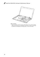
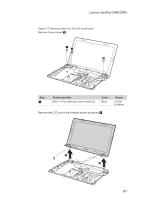
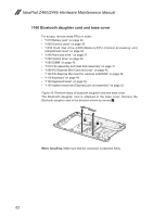
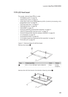
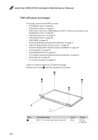
Lenovo IdeaPad Z460/Z465 1170 LCD front bezel For access, remove these FRUs in order: •• "1010 Battery pack" on page 34 •• "1020 Dummy cards" on page 35 •• "1030 Hard disk drive (HDD)/Memory/CPU (Central processing unit) compartment cover" on page 36 •• "1040 Hard disk drive " on page 37 •• "1050 Optical drive" on page 39 •• "1060 DIMM" on page 40 •• "1070 Fan assembly and Heat Sink assembly" on page 41 •• "1090 PCI Express Mini Card slot cover" on page 45 •• "1100 PCI Express Mini Card for wireless LAN/WAN" on page 46 •• "1110 Keyboard" on page 48 •• "1120 Keyboard bezel" on page 50 •• "1140 System board and ExpressCard slot assembly" on page 55 •• "1150 LCD unit" on page 59 Figure 17. Removal steps of LCD front bezel Remove two screws 1. Step 1 Screw (quantity) M2.5 × 5 mm, flat-head, nylon-coated (2) Color Silver Torque 0.6 Nm (6 kgfcm) Remove the LCD front bezel in the direction shown by arrows 2. 2 2 2 2 65
-
 1
1 -
2
-
3
-
4
-
5
-
6
-
7
-
8
-
9
-
10
-
11
-
12
-
13
-
14
-
15
-
16
-
17
-
18
-
19
-
20
-
21
-
22
-
23
-
24
-
25
-
26
-
27
-
28
-
29
-
30
-
31
-
32
-
33
-
34
-
35
-
36
-
37
-
38
-
39
-
40
-
41
-
42
-
43
-
44
-
45
-
46
-
47
-
48
-
49
-
50
-
51
-
52
-
53
-
54
-
55
-
56
-
57
-
58
-
59
-
60
-
61
-
62
-
63
-
 64
64 -
 65
65 -
 66
66 -
 67
67 -
 68
68 -
 69
69 -
 70
70 -
 71
71 -
 72
72 -
 73
73 -
 74
74 -
75
-
76
-
77
-
78
-
79
-
80
-
81
-
82
-
83
-
84
-
85
-
86
-
87
-
88
-
89
-
90
-
91
-
92
 |
 |