Lenovo K300 Lenovo IdeaCentre K3 Series Hardware Maintenance Manual
Lenovo K300 - IdeaCentre - 5316 Manual
 |
UPC - 884942469558
View all Lenovo K300 manuals
Add to My Manuals
Save this manual to your list of manuals |
Lenovo K300 manual content summary:
- Lenovo K300 | Lenovo IdeaCentre K3 Series Hardware Maintenance Manual - Page 1
safety...4 Electrical safety...5 Safety inspection guide 7 Handling electrostatic discharge-sensitive devices 8 Grounding requirements 8 Safety notices...9 Chapter 3. General information 12 Specifications...12 Chapter 4. General Checkout 13 Problem determination tips 14 Chapter 5. Using - Lenovo K300 | Lenovo IdeaCentre K3 Series Hardware Maintenance Manual - Page 2
Index 22 Hard disk drive boot error 22 Power Supply Problems 23 Beep symptoms 24 POST error codes 25 Undetermined problems 27 Chapter 7. Replacing hardware 28 General information 28 Removing the computer cover 29 Removing the front bezel 30 Replacing a memory module 31 Replacing the hard - Lenovo K300 | Lenovo IdeaCentre K3 Series Hardware Maintenance Manual - Page 3
About this manual 1Chapter 1. About this manual This manual contains service and reference information for Lenovo IdeaCentre K computers listed on the cover. It is intended only for trained servicers who are familiar with Lenovo computer products. Before servicing a Lenovo product, be sure to read - Lenovo K300 | Lenovo IdeaCentre K3 Series Hardware Maintenance Manual - Page 4
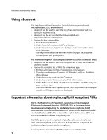
Manual Using eSupport For Key Commodities (Examples - hard disk drive, system board, microprocessor, LCD, and memory) •• eSupport can be used to view the list of key commodities built in a particular machine serial. •• eSupport can be accessed at the following Web site: http://www.lenovo.com/support - Lenovo K300 | Lenovo IdeaCentre K3 Series Hardware Maintenance Manual - Page 5
to be ready to support Lenovo's requirements and schedule. Products sold in 2005, will contain some RoHS compliant FRUs. The following statement pertains to these products and any product Lenovo produces containing RoHS compliant parts. RoHS compliant Lenovo IdeaCentre K parts have unique FRU - Lenovo K300 | Lenovo IdeaCentre K3 Series Hardware Maintenance Manual - Page 6
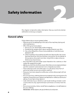
Hardware Maintenance Manual Safety information 2 This chapter contains the safety information that you need to be familiar with before servicing a computer. General safety Follow these rules to ensure general safety: •• Observe good housekeeping in the area of the machines during and after - Lenovo K300 | Lenovo IdeaCentre K3 Series Hardware Maintenance Manual - Page 7
be hazardous to your eyes. •• After service, reinstall all safety shields, guards, power cords, telecommunication systems, networks, and modems before you open the server/workstation covers, unless instructed all power before: - Performing a mechanical inspection - Working near power supplies - - Lenovo K300 | Lenovo IdeaCentre K3 Series Hardware Maintenance Manual - Page 8
safety precautions when you work with very high voltages; these instructions are in the safety sections of maintenance information. Use extreme •• Do not service the following parts with the power on when they are removed from their normal operating places in a machine: - Power supply units - Pumps - Lenovo K300 | Lenovo IdeaCentre K3 Series Hardware Maintenance Manual - Page 9
The guide consists of a series of steps presented in a checklist. Begin the checks with the power off, and the power cord disconnected. Checklist: 1. Check exterior covers for damage (loose, broken, or sharp edges). 2. Power-off the computer. Disconnect the power cord. 3. Check the power cord - Lenovo K300 | Lenovo IdeaCentre K3 Series Hardware Maintenance Manual - Page 10
Hardware Maintenance Manual Handling electrostatic discharge-sensitive devices Any computer part containing transistors or integrated a grounding system, such as those listed below, to provide protection that meets the specific service requirement. Note: The use of a grounding system is desirable - Lenovo K300 | Lenovo IdeaCentre K3 Series Hardware Maintenance Manual - Page 11
when there is evidence of fire, water, or structural damage. •• Disconnect the attached power cords, telecommunications systems, networks, and modems before you open the device covers, unless instructed otherwise in the installation and configuration procedures. •• Connect and disconnect cables as - Lenovo K300 | Lenovo IdeaCentre K3 Series Hardware Maintenance Manual - Page 12
Manual CAUTION: When replacing the lithium battery, use only Part Number 33F8354 or an equivalent type battery recommended by the manufacturer. If your system CAUTION: When laser products (such as CD-ROMs, DVD-ROM drives, fiber optic laser radiation. There are no serviceable parts inside the device. - Lenovo K300 | Lenovo IdeaCentre K3 Series Hardware Maintenance Manual - Page 13
CAUTION: Use safe practices when lifting. CAUTION: The power control button on the device and the power switch on the power supply do not turn off the electrical current supplied to the device. The device also might have more than one power cord. To remove all electrical current from the device - Lenovo K300 | Lenovo IdeaCentre K3 Series Hardware Maintenance Manual - Page 14
Maintenance Manual General information 3 This chapter provides general information that applies to all machine types supported by this publication. Specifications This section lists the physical specifications for your computer. Type IdeaCentre K3 This section lists the physical specifications - Lenovo K300 | Lenovo IdeaCentre K3 Series Hardware Maintenance Manual - Page 15
appear if a problem or conflict is found by an application program, the operating system, or both. For an explanation of these messages, refer to the information supplied with that software package. Notes • The default is for this computer to boot up in quiet mode (no beep, no memory count and - Lenovo K300 | Lenovo IdeaCentre K3 Series Hardware Maintenance Manual - Page 16
software combinations that can be encountered, use the following information to assist you in problem determination. If possible, have this information available when requesting assistance from Service Support and Engineering functions. •• Machine type and model •• Processor or hard disk upgrades - Lenovo K300 | Lenovo IdeaCentre K3 Series Hardware Maintenance Manual - Page 17
Chapter 4. General Checkout Comparing the configuration and software set-up between "working and non-working" systems will often lead to problem resolution. 15 - Lenovo K300 | Lenovo IdeaCentre K3 Series Hardware Maintenance Manual - Page 18
the F1 key. Notes: a. If you are using a USB keyboard and the Setup Utility program does not display using this method, repeatedly press and release the F1 key rather than leaving it pressed when turning on the computer. b. If a power-on password or an administrator password has been set, the Setup - Lenovo K300 | Lenovo IdeaCentre K3 Series Hardware Maintenance Manual - Page 19
case sensitive • Not be your name or your user name • Not be a common word or a computers, you might want to set a Administrator Password. After you set a Administrator Password, a password prompt is displayed each time you try to access the Setup Utility program. If both the administrator and power - Lenovo K300 | Lenovo IdeaCentre K3 Series Hardware Maintenance Manual - Page 20
. 2. when you type the Administrator password. a message will display that Enter New Password. Press Enter and a message will display that indicates the password has been disabled. After that, the poweron password will be disabled too if a power-on password has been installed. 3. Press any key to - Lenovo K300 | Lenovo IdeaCentre K3 Series Hardware Maintenance Manual - Page 21
Enter. 2. when you type the power-on password. a message will display that Enter New Password. Press Enter and a message will display that indicates the password has been disabled. 3. Press any key to contine. Using Device Device is used to enable or disable user access to the following device - Lenovo K300 | Lenovo IdeaCentre K3 Series Hardware Maintenance Manual - Page 22
boot device. Note: Not all CDs, hard disks, and diskettes are bootable. 1. Turn off your computer. 2. Press and hold the F12 key then turn on the computer. When the Startup Device Menu appears, release the F12 key. Note: If you are using a USB keyboard and the Startup Device Menu does not display - Lenovo K300 | Lenovo IdeaCentre K3 Series Hardware Maintenance Manual - Page 23
settings, press Esc to return to the Setup Utility program menu (you might have to press Esc several times). If you want to save the new settings, select Save changes and Exit before you exit. Otherwise, your changes will not be saved. 21 - Lenovo K300 | Lenovo IdeaCentre K3 Series Hardware Maintenance Manual - Page 24
page 13. This index can also be used to help you decide which FRUs to have available when servicing a computer. If you are unable to correct the problem using this index, go to "Undetermined problems" on page 27. Notes • If you have both an error message and an incorrect audio response diagnose the - Lenovo K300 | Lenovo IdeaCentre K3 Series Hardware Maintenance Manual - Page 25
drive. Power Supply Problems If you suspect a power problem, use the following procedures. Check/Verify FRU/Action Check the following for proper Reseat connectors installation. •• Power Cord •• On/Off Switch connector •• On/Off Switch Power Supply connector •• System Board Power Supply - Lenovo K300 | Lenovo IdeaCentre K3 Series Hardware Maintenance Manual - Page 26
until the problem happens again. This will reveal the malfunctioning card. 8 beeps If the system video adapter is an Display memory error (system video add-in card, replace or reseat the adapter) video adapter. If the video adapter is an integrated part of the system board, the board may be - Lenovo K300 | Lenovo IdeaCentre K3 Series Hardware Maintenance Manual - Page 27
system and some options. This series of tests is called the Power-On Self-Test, or POST. POST does the following operations. • Checks some basic system-board operations • Checks the memory operation • Starts the video operation • Verifies that the boot drive is working If the POST detects a problem - Lenovo K300 | Lenovo IdeaCentre K3 Series Hardware Maintenance Manual - Page 28
. The BIOS then ignores the missing keyboard during POST. The system has been halted. A reset or power cycle is required to reboot the machine. This message appears after a fatal error has been detected. Pressing the TAB key permits the user to toggle between the default POST display screen and - Lenovo K300 | Lenovo IdeaCentre K3 Series Hardware Maintenance Manual - Page 29
d. Extended video memory e. External Cache f. External Cache RAM g. Hard disk drive h. Diskette drive 3. Power-on the computer to re-test the system. 4. Repeat steps 1 through 3 until you find the failing device or adapter. If all devices and adapters have been removed, and the problem continues - Lenovo K300 | Lenovo IdeaCentre K3 Series Hardware Maintenance Manual - Page 30
or in the Hardware Maintenance Manual (HMM) for the computer. To obtain copies of the Safety and Warranty Guide or HMM, go to the Support Web site at http://consumersupport.lenovo.com Note Use only parts provided by Lenovo. General information Pre-disassembly instructions Before proceeding with the - Lenovo K300 | Lenovo IdeaCentre K3 Series Hardware Maintenance Manual - Page 31
to let the computer cool before removing the computer cover. To remove the computer cover: 1. Remove any media (diskettes, CDs, or memory cards) from the drives, shut down your operating system, turn off all attached devices, and the computer. 2. Unplug all power cords from electrical outlets - Lenovo K300 | Lenovo IdeaCentre K3 Series Hardware Maintenance Manual - Page 32
Hardware Maintenance Manual Removing the front bezel To remove the front bezel: 1. Remove the computer cover. Refer to "Removing the computer cover". Note For this procedure, it helps to lay the computer on its side. 2. Remove the front bezel by releasing the three plastic tabs inside the chassis - Lenovo K300 | Lenovo IdeaCentre K3 Series Hardware Maintenance Manual - Page 33
reading the "Important safety information" in the Safety and Warranty Guide that was included with your computer or in the Hardware Maintenance Manual (HMM) for the computer. To obtain copies of the Safety and Warranty Guide or HMM, go to the Support Web site at http://consumersupport.lenovo.com 31 - Lenovo K300 | Lenovo IdeaCentre K3 Series Hardware Maintenance Manual - Page 34
being replaced by opening the retaining clips as shown. 4. Position the new memory module over the memory connector. Make sure the notch on the memory aligns correctly with the connector key on the system board. Push the memory module straight down into the connector until the retaining clips close - Lenovo K300 | Lenovo IdeaCentre K3 Series Hardware Maintenance Manual - Page 35
information" in the Safety and Warranty Guide that was included with your computer or in the Hardware Maintenance Manual (HMM) for the computer. To obtain copies of the Safety and Warranty Guide or HMM, go to the Support Web site at http://consumersupport.lenovo.com To replace the hard disk drive - Lenovo K300 | Lenovo IdeaCentre K3 Series Hardware Maintenance Manual - Page 36
Hardware Maintenance Manual 4. Slide the new hard disk drive into the drive bay. 5. Pivot in the drive bay in place. 6. Connect the power and signal cables to the hard disk drive. Refer to "Identifying parts on the system board". 7. Refer to the "Completing the installation". Replacing an optical - Lenovo K300 | Lenovo IdeaCentre K3 Series Hardware Maintenance Manual - Page 37
reading the "Important safety information" in the Safety and Warranty Guide that was included with your computer or in the Hardware Maintenance Manual (HMM) for the computer. To obtain copies of the Safety and Warranty Guide or HMM, go to the Support Web site at http://consumersupport.lenovo.com 35 - Lenovo K300 | Lenovo IdeaCentre K3 Series Hardware Maintenance Manual - Page 38
Hardware Maintenance Manual To replace the system fan assembly: 1. Remove the computer cover. Refer to "Removing the computer cover". 2. Locate the system fan assembly. Refer to "Identifying parts on the system board". 3. Disconnect the system fan assembly cable from the system board. Refer to" - Lenovo K300 | Lenovo IdeaCentre K3 Series Hardware Maintenance Manual - Page 39
and push the rubber mounts through the holes. 6. Pull on the tips of the rubber mounts until the fan assembly is in place. 7. Connect the system fan assembly cable to the system fan connector on the system board. 8. Refer to the "Completing the installation". 37 - Lenovo K300 | Lenovo IdeaCentre K3 Series Hardware Maintenance Manual - Page 40
Warranty Guide or HMM, go to the Support Web site at http://consumersupport.lenovo.com To replace the heat sink assembly: 1. Remove the computer cover. Refer to "Removing the computer cover". 2. Lay the computer on its side. 3. Locate the heat sink. Refer to "Identifying parts on the system board - Lenovo K300 | Lenovo IdeaCentre K3 Series Hardware Maintenance Manual - Page 41
information" in the Safety and Warranty Guide that was included with your computer or in the Hardware Maintenance Manual (HMM) for the computer. To obtain copies of the Safety and Warranty Guide or HMM, go to the Support Web site at http://consumersupport.lenovo.com To replace an adapter: 1. Remove - Lenovo K300 | Lenovo IdeaCentre K3 Series Hardware Maintenance Manual - Page 42
Hardware Maintenance Manual 2. At the rear of the computer, press the release button to open the adapter latch and remove the adapter by pulling it straight out of the adapter connector. 40 - Lenovo K300 | Lenovo IdeaCentre K3 Series Hardware Maintenance Manual - Page 43
Chapter 7. Replacing hardware 3. Install the new adapter into the same adapter connector. 4. Ensure the adapter is fully seated into the adapter connector. 5. At the rear of the computer, pivot the adapter latch to the closed position to secure the adapter. 6. Refer to the "Completing the - Lenovo K300 | Lenovo IdeaCentre K3 Series Hardware Maintenance Manual - Page 44
Hardware Maintenance Manual Note 1 eplacement of some models equipped with graphic adapter bracket is different. plastic bracket out of the chassis. 3. Then remove the adapter as above. After the Graphic Adapter is installed , install the bracket as the following: 1. Install the plastic bracket into - Lenovo K300 | Lenovo IdeaCentre K3 Series Hardware Maintenance Manual - Page 45
7. Replacing hardware 2. Install the two screws to secure the plastic bracket. Note Use only the screws provided by Lenovo. Note 2 Replacement of some models equipped with graphic adapter bracket is different. Please remove the bracket first as the following: 1. Remove the screw that secures the - Lenovo K300 | Lenovo IdeaCentre K3 Series Hardware Maintenance Manual - Page 46
Hardware Maintenance Manual 2. Press the pin on one end of the metal bracket and pull the metal bracket straight out of the chassis. After the Graphic Adapter is installed, install the bracket as the following: 1. Install the metal bracket into the chassis so that the screw hole in the metal bracket - Lenovo K300 | Lenovo IdeaCentre K3 Series Hardware Maintenance Manual - Page 47
reading the "Important safety information" in the Safety and Warranty Guide that was included with your computer or in the Hardware Maintenance Manual (HMM) for the computer. To obtain copies of the Safety and Warranty Guide or HMM, go to the Support Web site at http://consumersupport.lenovo.com 45 - Lenovo K300 | Lenovo IdeaCentre K3 Series Hardware Maintenance Manual - Page 48
Hardware Maintenance Manual To replace an CPU 1. Remove the computer cover. Refer to "Removing the computer cover". 2. Remove the front bezel. Refer to "Removing the front bezel". 3. Remove the system board. Refer to "Replacing the heat sink assembly". 4. Remove the heat sink and fan assembly. Refer - Lenovo K300 | Lenovo IdeaCentre K3 Series Hardware Maintenance Manual - Page 49
microprocessor. This is important when reinstalling the microprocessor on the new system board. b. Do not drop anything onto the microprocessor socket while it the protective cover that protects the gold contacts on the new microprocessor . 9. Holding the microprocessor with your fingers, position - Lenovo K300 | Lenovo IdeaCentre K3 Series Hardware Maintenance Manual - Page 50
Hardware Maintenance Manual Important To avoid damaging the microprocessor contacts, do not tilt the microprocessor when installing it into the socket. 10. Lower the microprocessor straight down into the system board socket of the system board. 11. To secure the microprocessor in the socket, close - Lenovo K300 | Lenovo IdeaCentre K3 Series Hardware Maintenance Manual - Page 51
Chapter 7. Replacing hardware Replacing the keyboard To replace the keyboard: 1. Remove any media (diskettes, CDs, or memory cards) from the drives, shut down your operating system, and turn off all attached devices and the computer. 2. Unplug all power cords from electrical outlets. 3. Locate the - Lenovo K300 | Lenovo IdeaCentre K3 Series Hardware Maintenance Manual - Page 52
the computer. 5. Connect the new mouse cable to the connector. 6. Refer to the "Completing the installation." Replacing the External speaker 1. Remove any media (diskettes, CDs, or memory cards) from the drives, shut down the computer, and turn off all attached devices. 2. Unplug all power cords - Lenovo K300 | Lenovo IdeaCentre K3 Series Hardware Maintenance Manual - Page 53
computer cover and reconnect cables, including telephone lines and power cords. Also, depending on the part that was replaced, you might need to confirm the updated information in the Setup Utility program. Refer to "Starting the Setup Utility" in the User Guide or in the Hardware Maintenance Manual - Lenovo K300 | Lenovo IdeaCentre K3 Series Hardware Maintenance Manual - Page 54
" and "Locating connectors on the rear of the computer". 5. To update your configuration settings, refer to "Starting the Setup Utility" in the User Guide or in the Hardware Maintenance Manual. Note In most areas of the world, Lenovo requires the return of the defective CRU. Information about - Lenovo K300 | Lenovo IdeaCentre K3 Series Hardware Maintenance Manual - Page 55
all operating systems support ACPI BIOS mode. Automatic Power-On features The Automatic Power-On features within the Power Management menu allow you to enable and disable features that turn on the computer automatically. •• Wake On LAN: This future allow system wake up by Lan card and onboard lan - Lenovo K300 | Lenovo IdeaCentre K3 Series Hardware Maintenance Manual - Page 56
the product according to instructions and requirements described in the manuals included with your computer. Lenovo will not assume responsibility for any loss caused except that caused by the installation or operations carried out by Lenovo professional service staff. Lenovo has made every attempt - Lenovo K300 | Lenovo IdeaCentre K3 Series Hardware Maintenance Manual - Page 57
table above includes the logo and registered trademarks of Lenovo and its partners. Other registered trademarks mentioned in all the manuals included with your computer belong to the specific company respectively. The manual included with your computer is protected by copyright laws and rules. None
-
 1
1 -
 2
2 -
 3
3 -
 4
4 -
 5
5 -
 6
6 -
 7
7 -
8
-
9
-
10
-
11
-
12
-
13
-
14
-
15
-
16
-
17
-
18
-
19
-
20
-
21
-
22
-
23
-
24
-
25
-
26
-
27
-
28
-
29
-
30
-
31
-
32
-
33
-
34
-
35
-
36
-
37
-
38
-
39
-
40
-
41
-
42
-
43
-
44
-
45
-
46
-
47
-
48
-
49
-
50
-
51
-
52
-
53
-
54
-
55
-
56
-
57
 |
 |

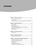
Contents
i
Contents
Chapter 1. About this manual
................................................
1
Important
Safety Information
......................................................................
1
Using eSupport
....................................................................................................
2
Important information about replacing RoHS compliant FRUs ..2
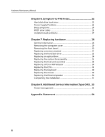
Chapter 2. Safety information
................................................
4
General safety
.......................................................................................................
4
Electrical safety
....................................................................................................
5
Safety inspection guide
...................................................................................
7
Handling electrostatic discharge-sensitive devices
.........................
8
Grounding requirements
...............................................................................
8
Safety notices
........................................................................................................
9
Chapter 3. General information
...........................................
12
Specifications
.....................................................................................................
12
Chapter 4. General Checkout
...............................................
13
Problem determination tips
......................................................................
14
Chapter 5. Using the Setup Utility (Type G43)
.................
16
Starting the Setup Utility program
.........................................................
16
Viewing and changing settings
................................................................
16
Using passwords
..............................................................................................
17
Using Device
......................................................................................................
19
Selecting a startup device
...........................................................................
20
Exiting from the Setup Utility program
................................................
21