Lenovo ThinkCentre M82 (English) User Guide - Page 72
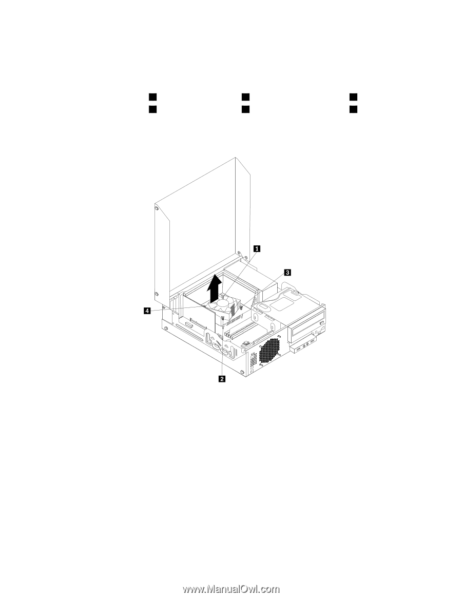
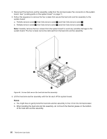
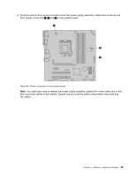
system board. The four screws cannot be removed from the heat sink and fan assembly.
 |
View all Lenovo ThinkCentre M82 manuals
Add to My Manuals
Save this manual to your list of manuals |
Page 72 highlights
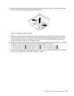
3. Disconnect the heat sink and fan assembly cable from the microprocessor fan connector on the system board. See "Locating parts on the system board" on page 11. 4. Follow this sequence to remove the four screws that secure the heat sink and fan assembly to the system board: a. Partially remove screw 1 , then fully remove screw 2 , and then fully remove screw 1 . b. Partially remove screw 3 , then fully remove screw 4 , and then fully remove screw 3 . Note: Carefully remove the four screws from the system board to avoid any possible damage to the system board. The four screws cannot be removed from the heat sink and fan assembly. Figure 45. Screws that secure the heat sink and fan assembly 5. Lift the heat sink and fan assembly with the fan duct off the system board. Notes: a. You might have to gently twist the heat sink and fan assembly to free it from the microprocessor. b. When handling the heat sink and fan assembly, do not touch the thermal grease on the bottom of the heat sink and fan assembly. 60 ThinkCentre User Guide
-
 1
1 -
2
-
3
-
4
-
5
-
6
-
7
-
8
-
9
-
10
-
11
-
12
-
13
-
14
-
15
-
16
-
17
-
18
-
19
-
20
-
21
-
22
-
23
-
24
-
25
-
26
-
27
-
28
-
29
-
30
-
31
-
32
-
33
-
34
-
35
-
36
-
37
-
38
-
39
-
40
-
41
-
42
-
43
-
44
-
45
-
46
-
47
-
48
-
49
-
50
-
51
-
52
-
53
-
54
-
55
-
56
-
57
-
58
-
59
-
60
-
61
-
62
-
63
-
64
-
65
-
66
-
 67
67 -
 68
68 -
 69
69 -
 70
70 -
 71
71 -
 72
72 -
 73
73 -
 74
74 -
 75
75 -
 76
76 -
 77
77 -
78
-
79
-
80
-
81
-
82
-
83
-
84
-
85
-
86
-
87
-
88
-
89
-
90
-
91
-
92
-
93
-
94
-
95
-
96
-
97
-
98
-
99
-
100
-
101
-
102
-
103
-
104
-
105
-
106
-
107
-
108
-
109
-
110
-
111
-
112
-
113
-
114
-
115
-
116
-
117
-
118
-
119
-
120
-
121
-
122
-
123
-
124
-
125
-
126
-
127
-
128
-
129
-
130
-
131
-
132
-
133
-
134
-
135
-
136
-
137
-
138
-
139
-
140
-
141
-
142
-
143
-
144
-
145
-
146
-
147
-
148
-
149
-
150
-
151
-
152
-
153
-
154
-
155
-
156
-
157
-
158
-
159
-
160
-
161
-
162
-
163
-
164
-
165
-
166
-
167
-
168
-
169
-
170
 |
 |