Lenovo ThinkCentre M92 (English) User Guide - Page 82
Replacing the cover presence switch
 |
View all Lenovo ThinkCentre M92 manuals
Add to My Manuals
Save this manual to your list of manuals |
Page 82 highlights
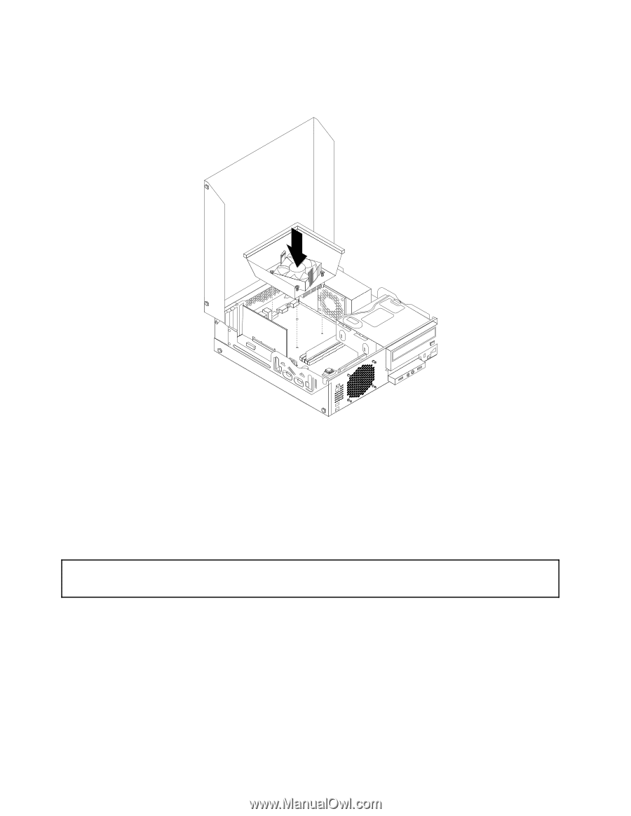
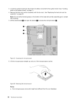
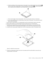
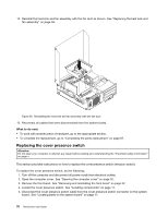
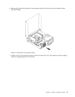
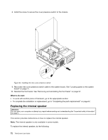
12. Reinstall the heat sink and fan assembly with the fan duct as shown. See "Replacing the heat sink and fan assembly" on page 59. Figure 56. Reinstalling the heat sink and fan assembly with the fan duct 13. Reconnect all cables that were disconnected from the system board. What to do next: • To work with another piece of hardware, go to the appropriate section. • To complete the replacement, go to "Completing the parts replacement" on page 87. Replacing the cover presence switch Attention: Do not open your computer or attempt any repair before reading and understanding the "Important safety information" on page v. This section provides instructions on how to replace the cover presence switch (intrusion switch). To replace the cover presence switch, do the following: 1. Turn off the computer and disconnect all power cords from electrical outlets. 2. Open the computer cover. See "Opening the computer cover" on page 32. 3. Remove the front bezel. See "Removing and reinstalling the front bezel" on page 32. 4. Locate the cover presence switch. See "Locating components" on page 11. 5. Disconnect the cover presence switch cable from the cover presence switch connector on the system board. See "Locating parts on the system board" on page 11. 70 ThinkCentre User Guide
-
 1
1 -
2
-
3
-
4
-
5
-
6
-
7
-
8
-
9
-
10
-
11
-
12
-
13
-
14
-
15
-
16
-
17
-
18
-
19
-
20
-
21
-
22
-
23
-
24
-
25
-
26
-
27
-
28
-
29
-
30
-
31
-
32
-
33
-
34
-
35
-
36
-
37
-
38
-
39
-
40
-
41
-
42
-
43
-
44
-
45
-
46
-
47
-
48
-
49
-
50
-
51
-
52
-
53
-
54
-
55
-
56
-
57
-
58
-
59
-
60
-
61
-
62
-
63
-
64
-
65
-
66
-
67
-
68
-
69
-
70
-
71
-
72
-
73
-
74
-
75
-
76
-
 77
77 -
 78
78 -
 79
79 -
 80
80 -
 81
81 -
 82
82 -
 83
83 -
 84
84 -
 85
85 -
 86
86 -
 87
87 -
88
-
89
-
90
-
91
-
92
-
93
-
94
-
95
-
96
-
97
-
98
-
99
-
100
-
101
-
102
-
103
-
104
-
105
-
106
-
107
-
108
-
109
-
110
-
111
-
112
-
113
-
114
-
115
-
116
-
117
-
118
-
119
-
120
-
121
-
122
-
123
-
124
-
125
-
126
-
127
-
128
-
129
-
130
-
131
-
132
-
133
-
134
-
135
-
136
-
137
-
138
-
139
-
140
-
141
-
142
-
143
-
144
-
145
-
146
-
147
-
148
-
149
-
150
-
151
-
152
-
153
-
154
-
155
-
156
-
157
-
158
-
159
-
160
-
161
-
162
-
163
-
164
-
165
-
166
-
167
-
168
-
169
-
170
 |
 |